Brushless motor and disk drive apparatus

Inactive Publication Date: 2013-11-28
NIDEC CORP
View PDF8 Cites 6 Cited by
  • Summary
  • Abstract
  • Description
  • Claims
  • Application Information

AI Technical Summary

Benefits of technology

[0010]According to another illustrative embodiment of the subject application, at least a portion of the magnet is accommodated within the recess portion. This helps restrain the axial dimension of the brushless motor from becoming larger. Moreover, a radial gap exists in at least one of a space between a radial inner end surface of the magnet and

Problems solved by technology

This makes it difficult for the magnetic fluxes to flow from the magnet toward the inner lower surface or the outer lower surface.
This ma

Method used


Image

  • Brushless motor and disk drive apparatus
  • Brushless motor and disk drive apparatus
  • Brushless motor and disk drive apparatus

Examples


Example

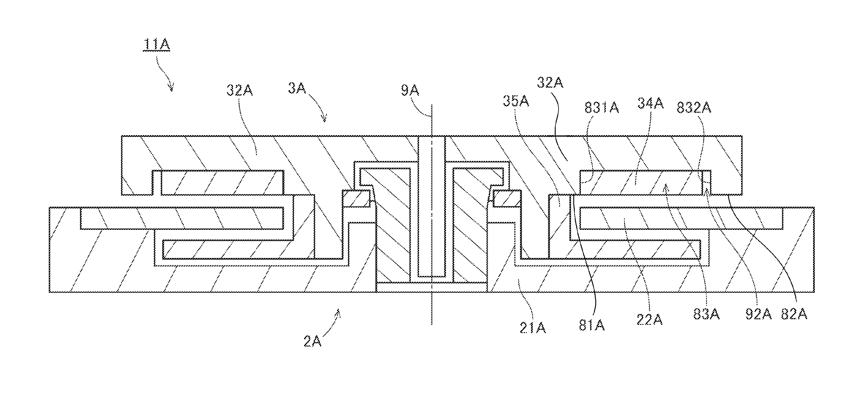
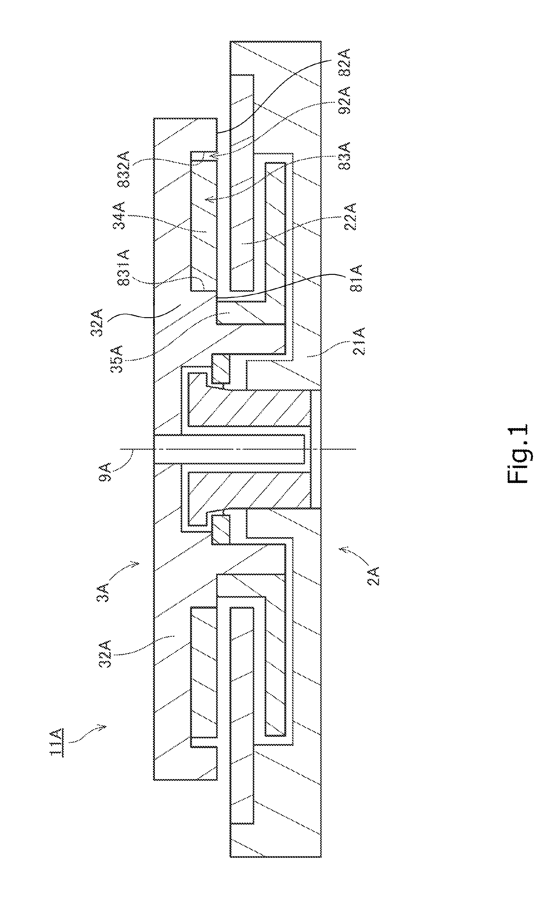
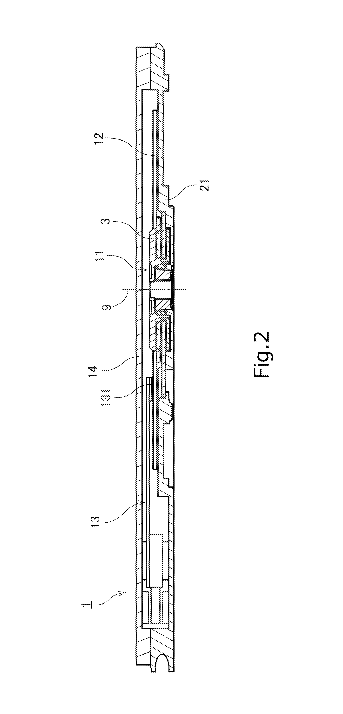
[0024]Hereinafter, illustrative embodiments of the present invention will now be described with reference to the accompanying drawings which form a part hereof. In the following description, the direction parallel to the center axis of a brushless motor will be referred to as “axial”. The direction orthogonal to the center axis of the brushless motor will be referred to as “radial”. The direction extending along an arc about the center axis of the brushless motor will be referred to as “circumferential”. In the following description, the shape and positional relationship of the respective portions will be described under the assumption that the axial direction extends in an up-down direction and that the side of a magnet with respect to an armature is an upper side. However, such definition of the up-down direction is not intended to limit the in-use direction of the brushless motor and the disk drive apparatus according to the present invention.

[0025]In the following description, t...


PUM


Abstract

A brushless motor includes a stationary unit and a rotary unit rotatably supported with respect to the stationary unit. The stationary unit includes an armature and a base member arranged to support the armature. The rotary unit includes a magnet, a hub made of a magnetic material and a rotor yoke made of a magnetic material. The armature includes a plurality of coil patterns arranged along a circumferential direction. The hub includes an inner lower surface, an outer lower surface and a recess portion. The recess portion is arranged between the inner lower surface and the outer lower surface and depressed upward. At least a portion of the magnet is accommodated within the recess portion. At least one of the inner lower surface and the outer lower surface is positioned above a lower surface of the magnet.

Description

BACKGROUND OF THE INVENTION[0001]1. Field of the Invention[0002]The present invention relates to a brushless motor and a disk drive apparatus.[0003]2. Description of the Related Art[0004]A hard disk apparatus is equipped with a brushless motor for rotating a disk. A conventional brushless motor is disclosed in, e.g., SG135981. A permanent-magnet synchronous motor of SG185981 includes a permanent magnet mounted to at least one of a top yoke and a bottom yoke and an armature arranged within an air gap between the permanent magnet and the other yoke (see claim 1).[0005]Referring to FIG. 4 of SG135981, a yoke is attached to a rotor shell. A permanent magnet is attached to the yoke. In this structure, the yoke is interposed between the rotor shell and the permanent magnet. For this reason, it becomes difficult to reduce the axial thickness of the motor. In an effort to make the motor thinner, there is provided, e.g., a structure in which a rotor shell is made of a magnetic material and i...

Claims


Application Information

Patent Timeline
IPC IPC(8): H02K1/27
CPCH02K1/2793H02K21/24H02K3/26H02K5/1677H02K15/03H02K1/2796G11B19/2009H02K1/27H02K1/28H02K3/28
Inventor HIMENO, TOSHIKAZUDU, HONGBINGHASHIMOTO, JUNICHIENOKIZONO, KAZUYA
Owner NIDEC CORP
Why Eureka
Try Eureka