
Vaccum die casting method and a die for vaccum die casting

a die casting and vacuum die technology, applied in the field of die casting methods and dies, can solve the problems of reducing the strength of the product, reducing the efficiency of the product, so as to achieve excellent productivity and suppress casting defects

Inactive Publication Date: 2021-05-06
HYUNDAI MOTOR CO LTD +1
View PDF0 Cites 1 Cited by
  • Summary
  • Abstract
  • Description
  • Claims
  • Application Information

AI Technical Summary

Benefits of technology

This patent describes a new method and device for vacuum die casting that allows for the manufacturing of high-quality and high-strength components without using expensive equipment. The device uses low-cost active oxygen and vacuum assist, and is simple to operate. It effectively removes air from the die, reducing casting defects and improving the quality of the final component. The method and device can be used in various industries, particularly in the automotive industry, where the trend towards motorization and eco-friendliness requires the use of high-performance components.

Problems solved by technology

In particular, in a case of a product having a complicated shape, it may be more difficult to discharge air, steam and residual gas in the cavity.
The air, steam and residual gas in the cavity, which are mixed in the molten metal, may cause a casting defect (blowhole, shrinkage defect, etc.) during cooling and solidification of the molten metal in the die, which lowers strength of the product.
It is impossible to heat treat a common die-casting component having a casting defect in the die.
However, the high vacuum equipment is very expensive, and the manufacturing cost is increased.

Method used


Image

  • Vaccum die casting method and a die for vaccum die casting
  • Vaccum die casting method and a die for vaccum die casting
  • Vaccum die casting method and a die for vaccum die casting

Examples


Embodiment Construction

[0035]In order to sufficiently understand the present disclosure, operational advantages of the present disclosure and objects accomplished by embodiments of the present disclosure, reference should be made to the accompanying drawings illustrating embodiments of the present disclosure and contents described in the accompanying drawings.

[0036]In describing embodiments of the present disclosure, detailed and repetitive descriptions for the known art related to the disclosure have been shortened or omitted where it may otherwise obscure the gist of the disclosure.

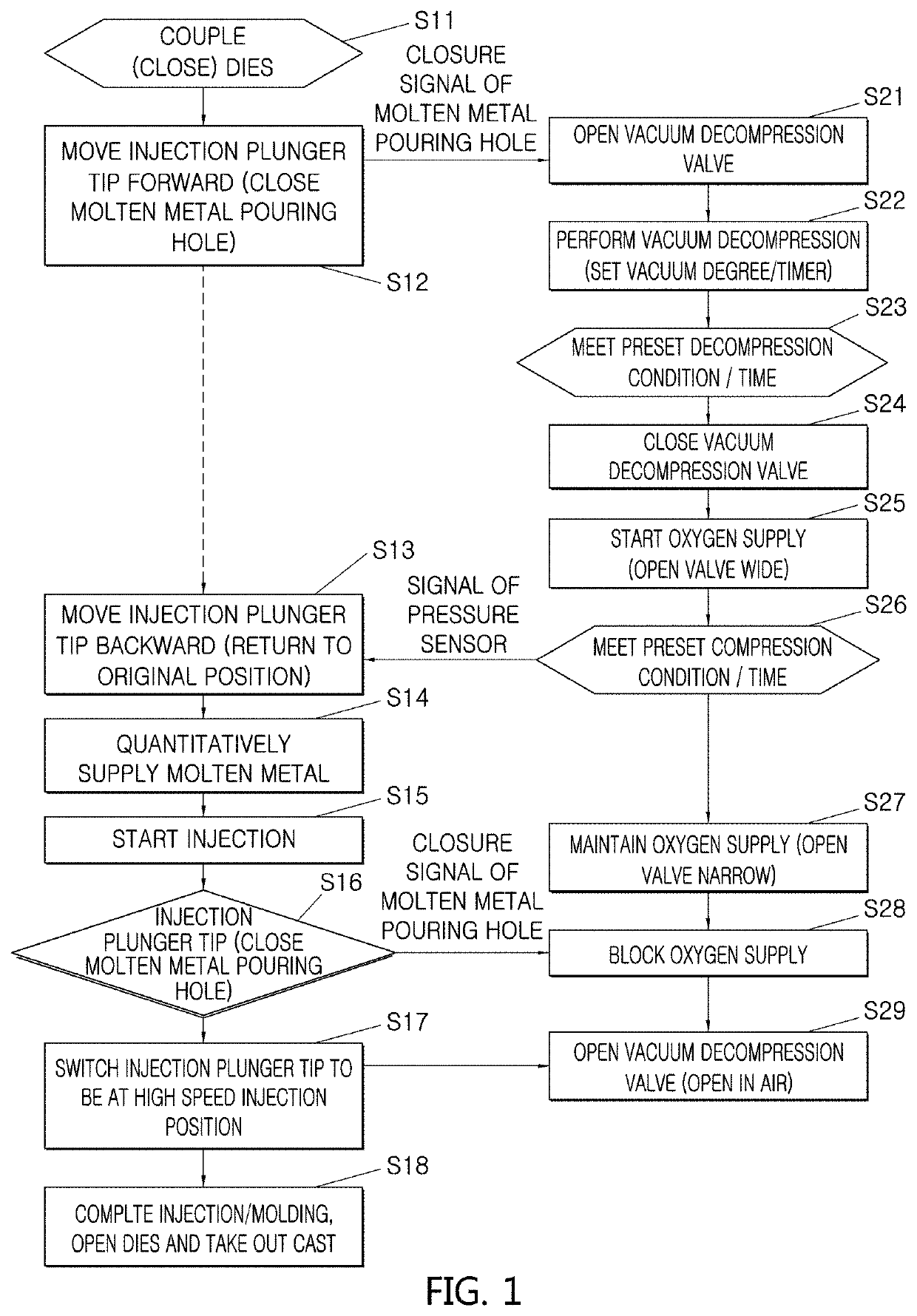
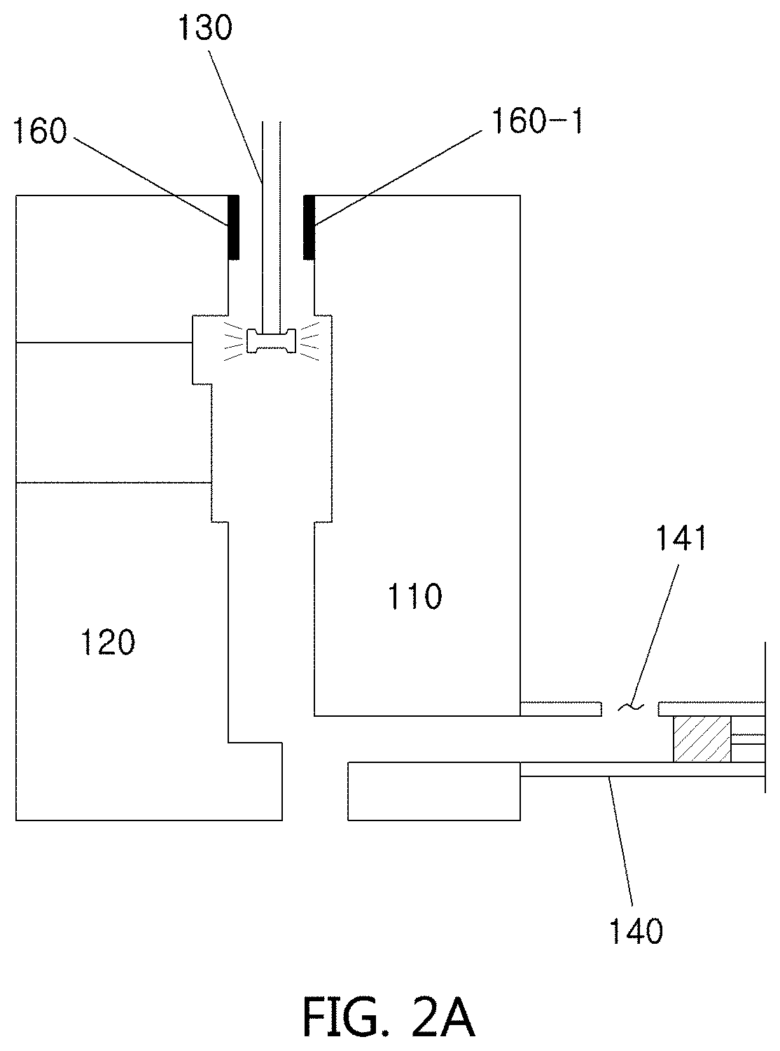
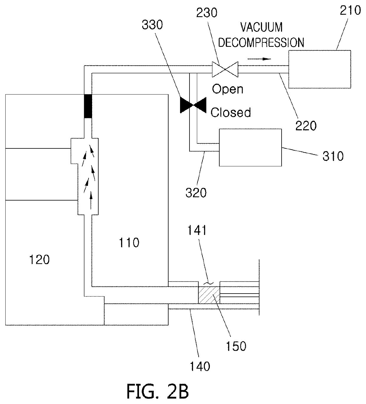
[0037]FIG. 1 is a flowchart illustrating a vacuum die casting method according to the present disclosure. FIGS. 2A, 2B, 2C, 2D, 2E, 2F and 2G sequentially illustrate a vacuum die casting method according to the present disclosure.

[0038]Hereinafter, a vacuum die casting method and a die for a vacuum die casting according to an embodiment of the present disclosure are described with reference to the flowchart of FIG. 1 and to t...


PUM

PropertyMeasurementUnit
Pressureaaaaaaaaaa
Pressureaaaaaaaaaa
Angleaaaaaaaaaa

Abstract

A vacuum die casting method may include: coupling a fixed die and a movable die to each other; closing a molten metal pouring hole formed in a sleeve using an injection plunger operated in the sleeve, which is formed on a lower side of the fixed die or the movable die; performing vacuum decompression in a cavity formed between the fixed die and the movable die using a vacuum decompression device connected to chill vent blocks provided on upper portions of the fixed die and the movable die; supplying oxygen in the cavity using an oxygen supply device connected to the chill vent blocks after completing the step of performing vacuum decompression; and supplying a molten metal to the cavity through the molten metal pouring hole.

Description

CROSS-REFERENCE(S) TO RELATED APPLICATIONS[0001]This application claims priority to Korean Patent Application No. 10-2019-0140352, filed on Nov. 5, 2019, which is incorporated herein by reference in its entirety.BACKGROUND OF THE DISCLOSUREField of the Disclosure[0002]The present disclosure relates to a die casting method and a die, and more particularly, relates to a die casting method and a die, in which the die is cast by creating a vacuum in cavity of the die.Description of the Related Art[0003]In general, a high pressure casting (die casting) may be performed in a manner whereby a molten metal, which is a melted lightweight non-ferrous metal alloy including aluminum, magnesium and zinc, is injected into a pouring hole of a pouring sleeve. The molten metal is filled into a cavity of a die by an injection plunger at high speed and high pressure, so that a die may be injection molded.[0004]In this process, gases filled in the cavity such as air and steam may be mixed together and ...

Claims


Application Information

Patent Timeline
IPC IPC(8): B22D17/14B22D17/00B22D17/04B22D17/06B22D17/22B22D17/20
CPCB22D17/145B22D17/002B22D17/2015B22D17/06B22D17/2218B22D17/04B22D17/14B22D17/22B22D17/32
Inventor JUNG, BYUNG-JUNELEE, JI-YONGLEE, CHEOL-UNGKIM, EOK-SOOPARK, JIN-YOUNGYOON, PIL-HWAN
Owner HYUNDAI MOTOR CO LTD
Learn More