Photoimaging

Active Publication Date: 2013-11-28
CJEK INTELLIGENT SOLUTIONS
View PDF2 Cites 3 Cited by
  • Summary
  • Abstract
  • Description
  • Claims
  • Application Information

AI Technical Summary

Benefits of technology

[0159]7. Exposure is much faster due to exclusion of air at the surface of the wet liquid photopolymer because of the film protection. This results in very rapid throughput in a normally slow cycle direct imaging unit e.g. laser direct imaging (LDI) units. Laser direct imaging (LDI) units cost about £500 k-£1 m and tim

Problems solved by technology

Although prior techniques exist in the art for producing thin lines suitable for forming electrical circuits such as PCBs, many of these techniques suffer from a number of significant disadvantages.
For example, many previous techniques suffer from poor resolution.
Moreover, techniques which do provide high resolution usually require complex apparatus.
A further problem is that previous techniques have required the use of dry films of photopolymer which are usually supported on a polyester (e.g. Mylar) film.
The thickness of these dry films has a detrimental effect on the resolution and/or definition of photoimaged surfaces as this allows unwanted undercutting (i.e. light shadowing) to occur during the photoimaging process.
There are also problems in adhering partially cured dry films to substrates and contamination problems which once again causes problems in the photoimaging process.
Dry films are also expensive when used in large quantities.
(1) Wet resist which is coated on a panel by a variety of means and then pre-dried with hot air to drive off the solvents. This leaves a ‘dry’ surface which is photo-imageable using UV light. The raw materials for wet resist are inexpensive but processing costs (heat etc) substantially add to the overall cost of using

Method used


Image

  • Photoimaging
  • Photoimaging
  • Photoimaging

Examples


Example

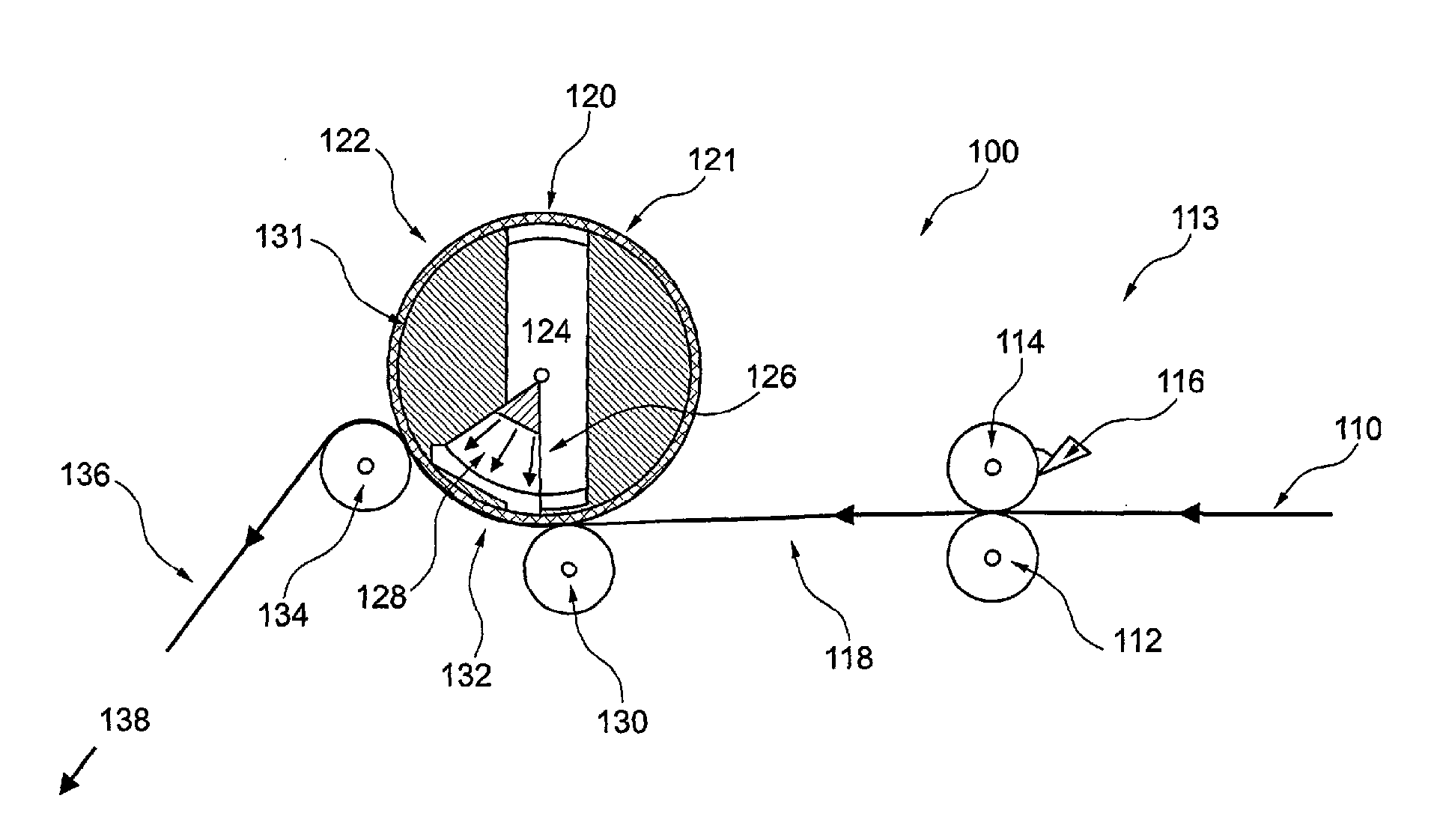
[0199]Generally speaking, the present invention resides in the provision of an improved photoimaging process wherein a rotatable phototool is used. In the present invention photoimaging process there is also no pre-drying prior to the actual imaging process—this is in contrast to prior art processes. The improved photoimaging process is based on the principle that liquid photopolymer (i.e. printable ink which can be imaged and cured) is not pre-dried prior to imaging and a rotatable phototool is used which allows reel to reel continuous process to be used. The parts of the photopolymer which are imaged are hardened and can then be used to form electrical circuitry. The photopolymer which is unexposed remains in liquid form can then be washed off.

[0200]In the prior art there are many circuits made by reel to reel production methods. Flexible circuits lend themselves to this method. Increasingly, high outputs of printed circuitry are required for the ‘printed electronics’ market. Reel...


PUM

PropertyMeasurementUnit
Lengthaaaaaaaaaa
Lengthaaaaaaaaaa
Lengthaaaaaaaaaa

Abstract

There is herein described a method and apparatus for photoimaging. More particularly, there is described a method and apparatus for photoimaging a substrate (e.g. a web) covered with a wet curable photopolymer wherein a rotatable phototool is pressed and rotated against the substrate to create an imaged substrate which is used to form images suitable for forming electrical circuits such as for printed circuit boards (PCBs), flat panel displays and flexible circuits. There is also described a method and apparatus for directly photoimaging a substrate covered with a wet curable photopolymer, wherein the photoimaged substrate is used to form images such as electrical circuits and a method and apparatus for exposing at least part of a solder mask on a printed circuit board (PCB) using a wet curable photopolymer wherein an imaging process may thereafter occur on the area above the solder mask.

Description

FIELD OF THE INVENTION[0001]The present invention relates to a method and apparatus for photoimaging a substrate. More particularly, the present invention relates to a method and apparatus for photoimaging (e.g. directly) a substrate such as a web covered with a liquid curable photopolymer wherein a rotatable phototool is pressed and rotated against the substrate to create an imaged substrate which is used to form images suitable for forming electrical circuits such as for printed circuit boards (PCBs), flat panel displays and flexible circuits. The present invention also relates to a method and apparatus for imaging and exposing at least part of a solder mask. More particularly, the present invention relates to a method and apparatus for imaging and exposing at least part of a solder mask on a substrate such as a printed circuit board (PCB) using a wet curable photopolymer wherein an imaging process may thereafter occur on the area above the solder mask.BACKGROUND OF THE INVENTION[...

Claims


Application Information

Patent Timeline
IPC IPC(8): G03F7/20
CPCG03F7/2012G03F7/2035H05K3/0082H05K3/064H05K3/3452H05K2203/0143H05K2203/107H05K2203/1545Y10T428/24802G03F7/20H01L21/67
Inventor KENNETT, CHARLES JONATHANCUNNINGHAM, JOHNGIBSON, ROBERT
Owner CJEK INTELLIGENT SOLUTIONS
Why Eureka
Try Eureka