Layer-3 overlay gateways

a layer 3 overlay and gateway technology, applied in the field of network management, can solve the problems of large switch size, high cost, physical space, power consumption, etc., and achieve the effect of increasing the cost of the switch, and increasing the complexity of the switch

Active Publication Date: 2013-11-28
AVAGO TECH INT SALES PTE LTD
View PDF3 Cites 249 Cited by
  • Summary
  • Abstract
  • Description
  • Claims
  • Application Information

AI Technical Summary

Problems solved by technology

However, the size of a switch cannot grow infinitely.
It is limited by physical space, power consumption, and design complexity, to name a few factors.
Furthermore, switches with higher capability are usually more complex and expensive.
More importantly, because an overly large and complex system often does not provide economy of scale, simply increasing the size and capability of a switch may prove economically unviable due to the increased per-port cost.
However, conventional layer-2 network architecture often cannot readily accommodate the dynamic nature of virtual machines.
While overlays bring many desirable features to a network, some issues remain unsolved in providing a logical subnet across layer-2 broadcast domains.

Method used


Image

  • Layer-3 overlay gateways
  • Layer-3 overlay gateways
  • Layer-3 overlay gateways

Examples


Embodiment Construction

[0034]The following description is presented to enable any person skilled in the art to make and use the invention, and is provided in the context of a particular application and its requirements. Various modifications to the disclosed embodiments will be readily apparent to those skilled in the art, and the general principles defined herein may be applied to other embodiments and applications without departing from the spirit and scope of the present invention. Thus, the present invention is not limited to the embodiments shown, but is to be accorded the widest scope consistent with the claims.

Overview

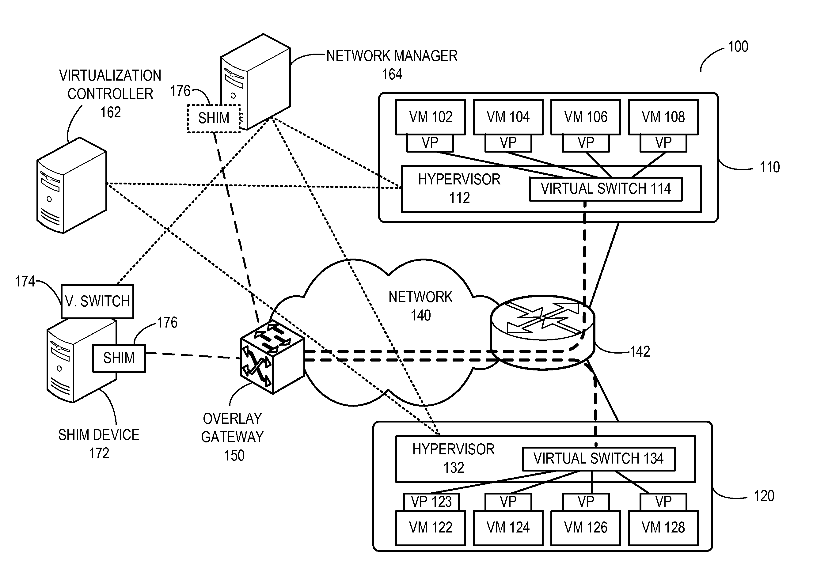
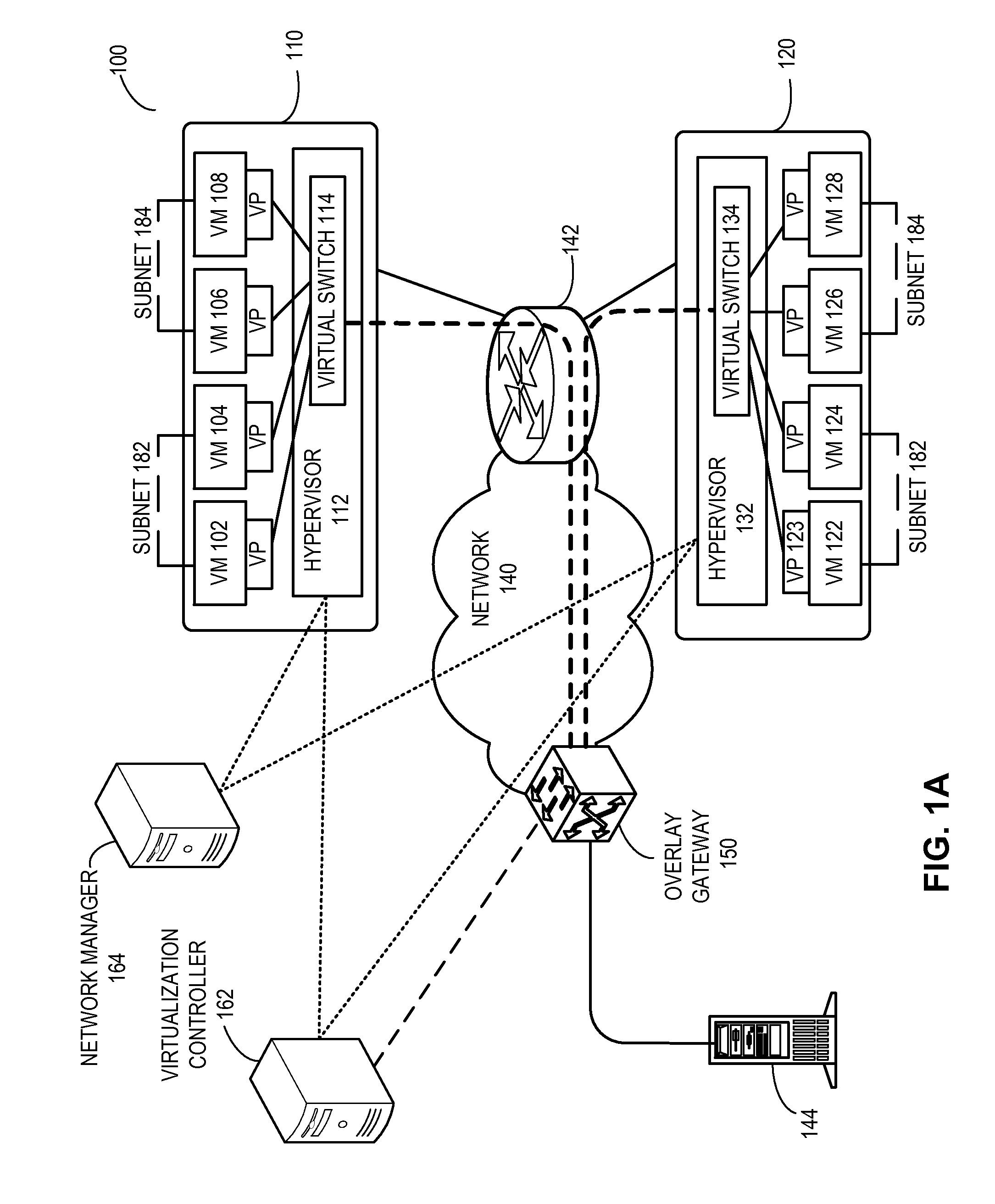
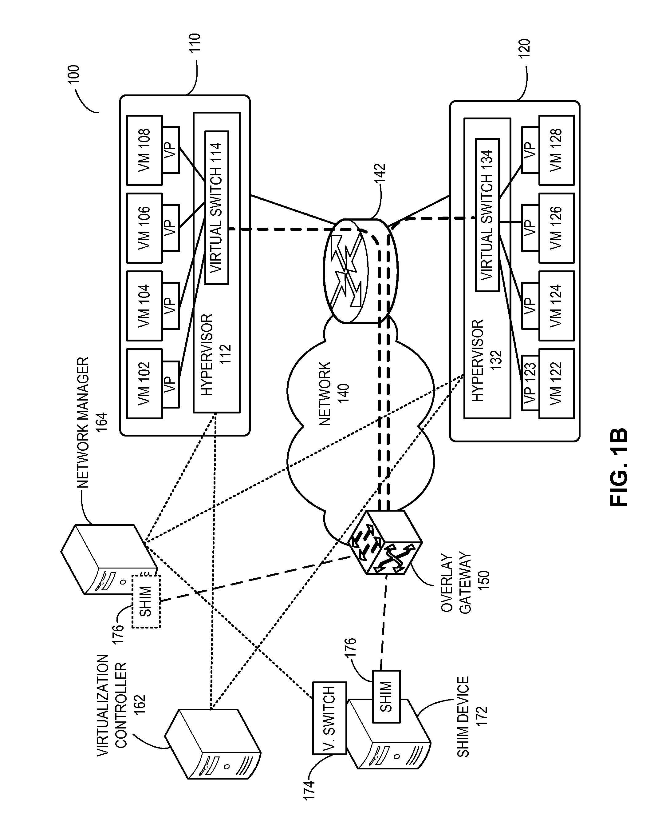
[0035]In embodiments of the present invention, the problem of facilitating a logical sub network (subnet) beyond a physical subnet boundary is solved by incorporating an overlay gateway which provides virtual tunneling between physical subnets to form the logical subnet. This logical subnet logically couples the virtual machines belonging to the logical subnet but residing in host mac...


PUM


Abstract

One embodiment of the present invention provides a computing system. The computing system includes a processor and a computer-readable storage medium for storing instructions. Based on the instructions, the processor operates the computing system as an overlay gateway. The computing system initiates and terminates an overlay tunnel associated with a virtual machine. During operation, the computing system maps a virtual Internet Protocol (IP) address of the virtual machine to a second IP address used to terminate the overlay tunnel based on information received from a configuration system. The computing system then determines an output port for a data packet based on the second IP address. The data packet comprises an inner packet and the destination address of this inner packet corresponds to the virtual IP address.

Description

RELATED APPLICATIONS[0001]This application claims the benefit of U.S. Provisional Application No. 61 / 650,943, Attorney Docket Number BRCD-3141.0.1.US.PSP, titled “L3 Overlay Gateways,” by inventor Mani Prasad Kancherla, filed 23 May 2012, the disclosure of which is incorporated by reference herein.[0002]The present disclosure is related to:[0003]U.S. Patent Publication No. 2010 / 0246388, Attorney Docket Number BRCD-112-0439US, titled “Redundant Host Connection in a Routed Network,” by inventors Somesh Gupta, Anoop Ghanwani, Phanidhar Koganti, and Shunjia Yu, filed 16 Mar. 2010; and[0004]U.S. patent application Ser. No. 13 / 801,858, Attorney Docket Number BRCD-3135.1.US.NP, titled “Overlay Tunnel in a Fabric Switch,” by inventor Phanidhar Koganti, filed 13 Mar. 2013;[0005]the disclosures of which are incorporated by reference herein.BACKGROUND[0006]1. Field[0007]The present disclosure relates to network management. More specifically, the present disclosure relates to layer-3 overlays i...

Claims


Application Information

Patent Timeline
Patent Type & Authority Applications(United States)
IPC IPC(8): H04L12/24
CPCH04L41/0806H04L49/70H04L12/4633H04L41/0803H04L41/0897
Inventor KANCHERLA, MANI PRASAD
Owner AVAGO TECH INT SALES PTE LTD
Why Eureka
Try Eureka