
Method for specifying fracture resistance of mechanically stressed glass or glass ceramic

a technology of mechanical stress and fracture resistance, applied in the direction of material strength using steady bending force, instruments, manufacturing tools, etc., can solve the problems of reducing the mechanical stress limit by two orders of magnitude, unable to reliably determine the long-term stability of materials, and requiring high reliability. , to achieve the effect of substantial weight savings

Active Publication Date: 2013-12-05
SCHOTT AG
View PDF0 Cites 7 Cited by
  • Summary
  • Abstract
  • Description
  • Claims
  • Application Information

AI Technical Summary

Benefits of technology

This patent describes a way to make components that are stronger and lighter than traditional components made from glass or glass ceramic. By assuming a predefined load and using a certain design method, the component can be made without failing during its minimum service life or surviving at least that amount of stress. This design method also allows for smaller dimensions of the component without compromising its reliability or performance. In simpler terms, this patent is about making components that are stronger and lighter than traditional components, which can be achieved by using a certain design method.

Problems solved by technology

There are so far no reliable methods known for determining the long-term stability of components made of materials whose stability is affected by the surface quality thereof.
However, this strength is considerably influenced by the surface quality, in particular by the presence of cracks on the surface.
Such cracks may reduce the mechanical stress limit by two orders of magnitude.
Furthermore, for some components a high reliability is required associated with a very low failure probability within a specified period of time which is different depending on the application.
This results in very uncertain data in a range of low failure probabilities.

Method used


Image

  • Method for specifying fracture resistance of mechanically stressed glass or glass ceramic
  • Method for specifying fracture resistance of mechanically stressed glass or glass ceramic
  • Method for specifying fracture resistance of mechanically stressed glass or glass ceramic

Examples


Embodiment Construction

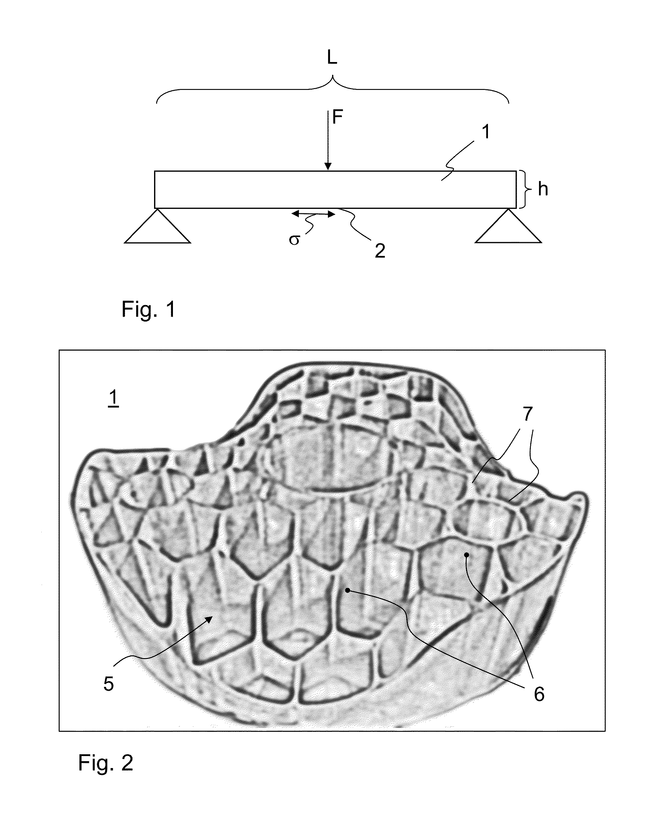
[0033]Referring to FIG. 1, one exemplary embodiment will be explained of how a value for the required mechanical strength may be determined when dimensioning the component, expressed as the maximum tensile stress occurring in the glass or glass ceramic material based on the mechanical stress occurring during use of the component.

[0034]The glass or glass ceramic component 1 in this exemplary embodiment is a carrier which is supported at both ends thereof. In this embodiment, the carrier is exposed to a force F at the center thereof. This causes a tensile stress σ at a surface 2 of the carrier, due to this mechanical load and associated deflection. In the ideal case, the resulting compressive stress at the other surface has the same magnitude. Since the tensile stress is more critical for the strength of glass or glass ceramic components, only this tensile stress will be considered below.

[0035]The following applies to the maximum tensile stress □max occurring at the central extreme fi...


PUM

PropertyMeasurementUnit
grain sizeaaaaaaaaaa
tensile stressaaaaaaaaaa

Abstract

A method for specifying the material of glass or glass ceramic components by either the minimum service life of a component as a function of a predefined mechanical stress or the mechanical resistance as a function of a predefined service life during which mechanical stress occurs. The method enables a leaner dimensioning of mechanically stressed glass and glass ceramic components.

Description

CROSS REFERENCE TO RELATED APPLICATIONS[0001]This application claims benefit under 35 U.S.C. §119(a) of German Patent Application No. 10 2012 104 594.1, filed May 29, 2012, the entire contents of which are incorporated herein by reference.BACKGROUND OF THE INVENTION[0002]1. Field of the Invention[0003]The invention generally relates to the characterization of material properties of products. More particularly, the invention relates to the determination of the resistance to fracture of mechanically stressed components, such as carrier structures.[0004]2. Description of Related Art[0005]There are so far no reliable methods known for determining the long-term stability of components made of materials whose stability is affected by the surface quality thereof. This criterion applies inter alia to brittle materials, such as glass and glass ceramics. Glass and glass ceramics are intrinsically very strong materials that break only under stresses where steel already failed. However, this st...

Claims


Application Information

Patent Timeline
Patent Type & Authority Applications(United States)
IPC IPC(8): G01N33/38G06F17/00
CPCG01N33/386G06F17/00G01N3/20G01N17/00G01N2203/0012G01N2203/0067G01N2203/0218G01N2203/0688C03C19/00C03B20/00
Inventor HARTMANN, PETER
Owner SCHOTT AG
Learn More