Controllable overrunning coupling

a coupling and control technology, applied in the direction of clutches, non-mechanical actuated clutches, freewheel clutches, etc., can solve the problems of high cost, heavy weight, and insufficient space for one-way clutches and brakes, and achieve the effect of reducing the cost and weight of the raceway and minimizing the space required for i

Active Publication Date: 2013-12-05
FORD GLOBAL TECH LLC
View PDF6 Cites 15 Cited by
  • Summary
  • Abstract
  • Description
  • Claims
  • Application Information

AI Technical Summary

Benefits of technology

[0010]The second pocket plate has the form of a circular arc, whose includes angle is substantially less than ninety degree, large enough to cont

Problems solved by technology

If centrifugal force were not employed in this way, the locking elements would wear prematurely and the spring duty cycle could c

Method used


Image

  • Controllable overrunning coupling
  • Controllable overrunning coupling
  • Controllable overrunning coupling

Examples


Embodiment Construction

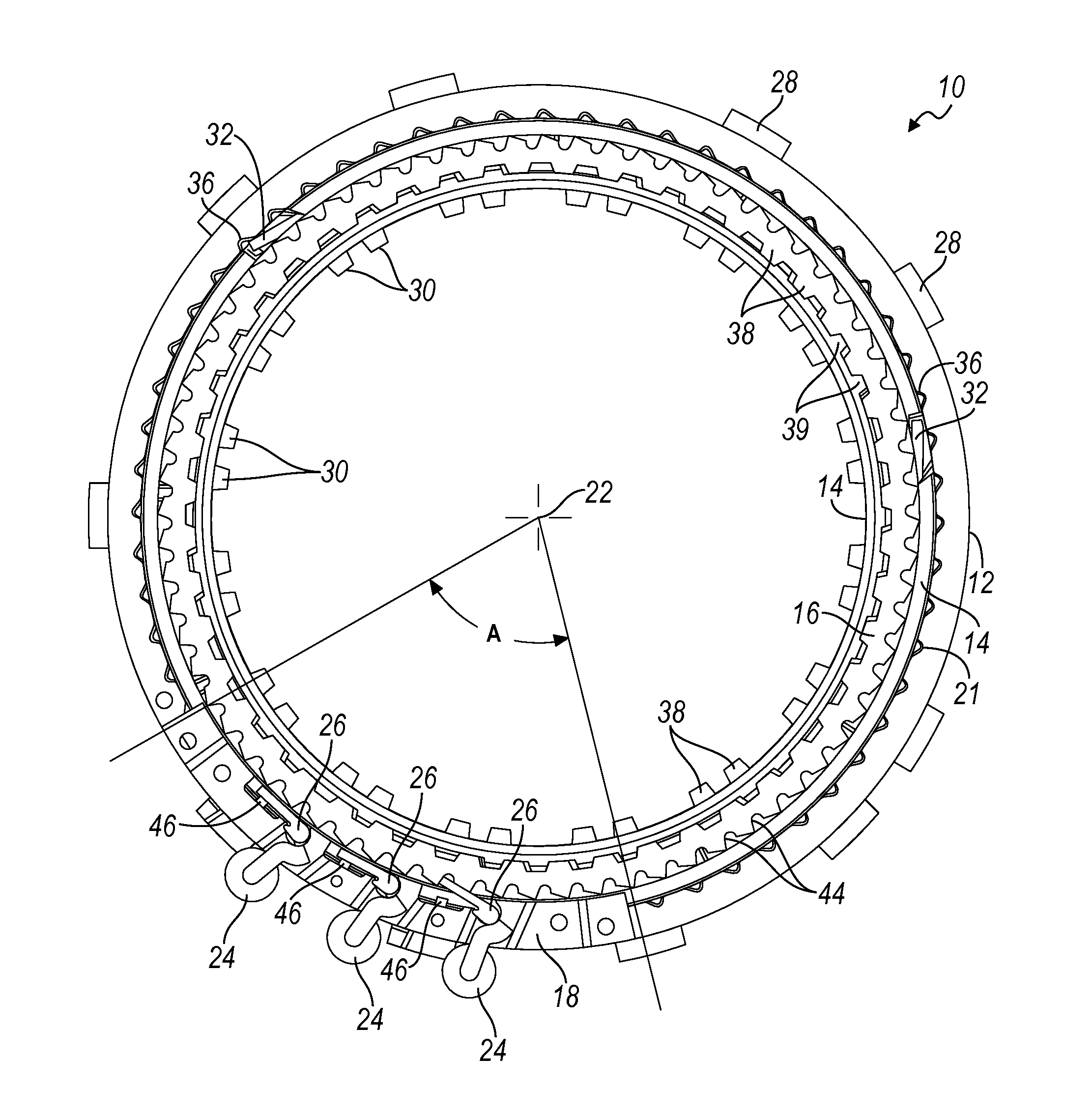
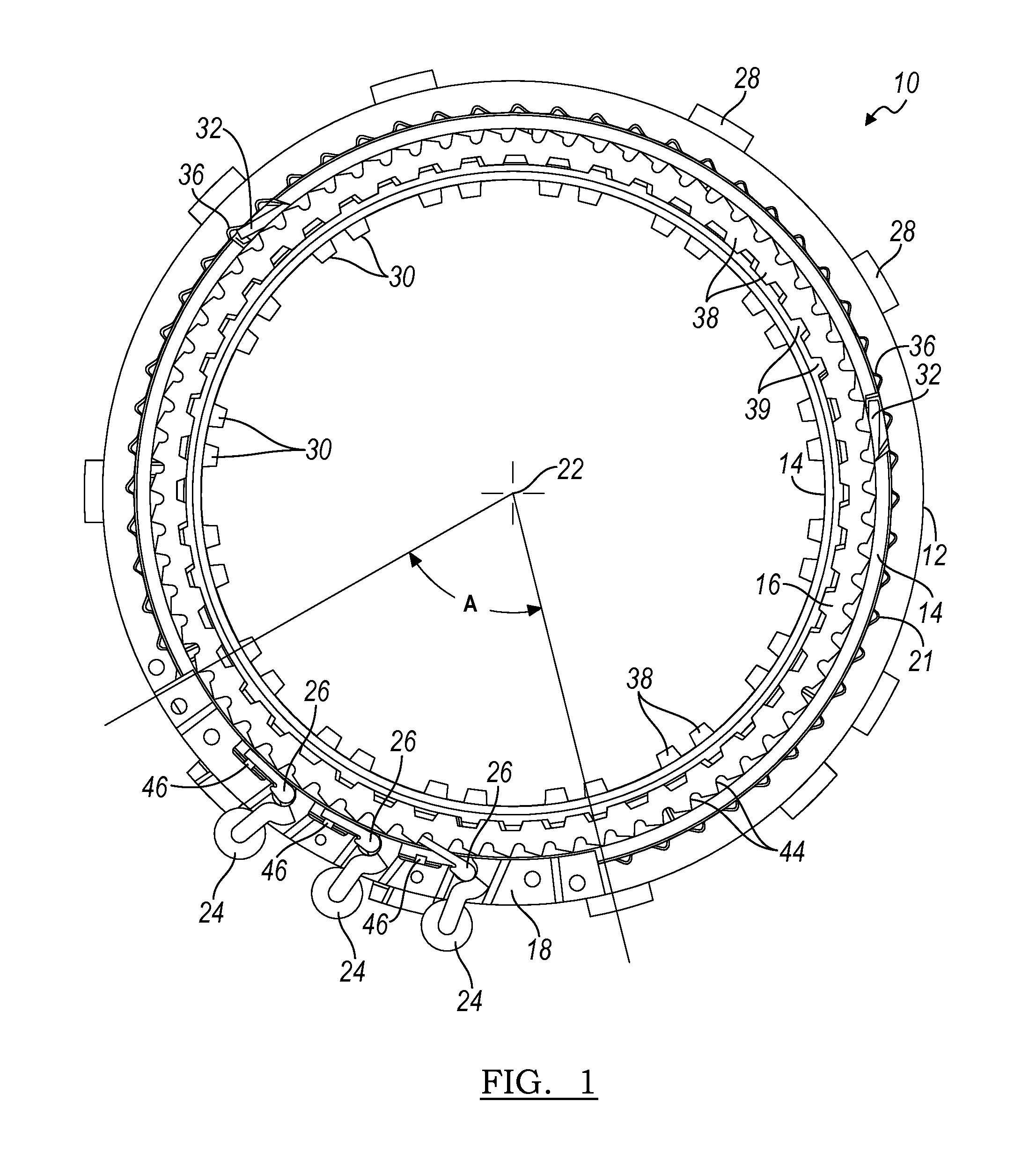
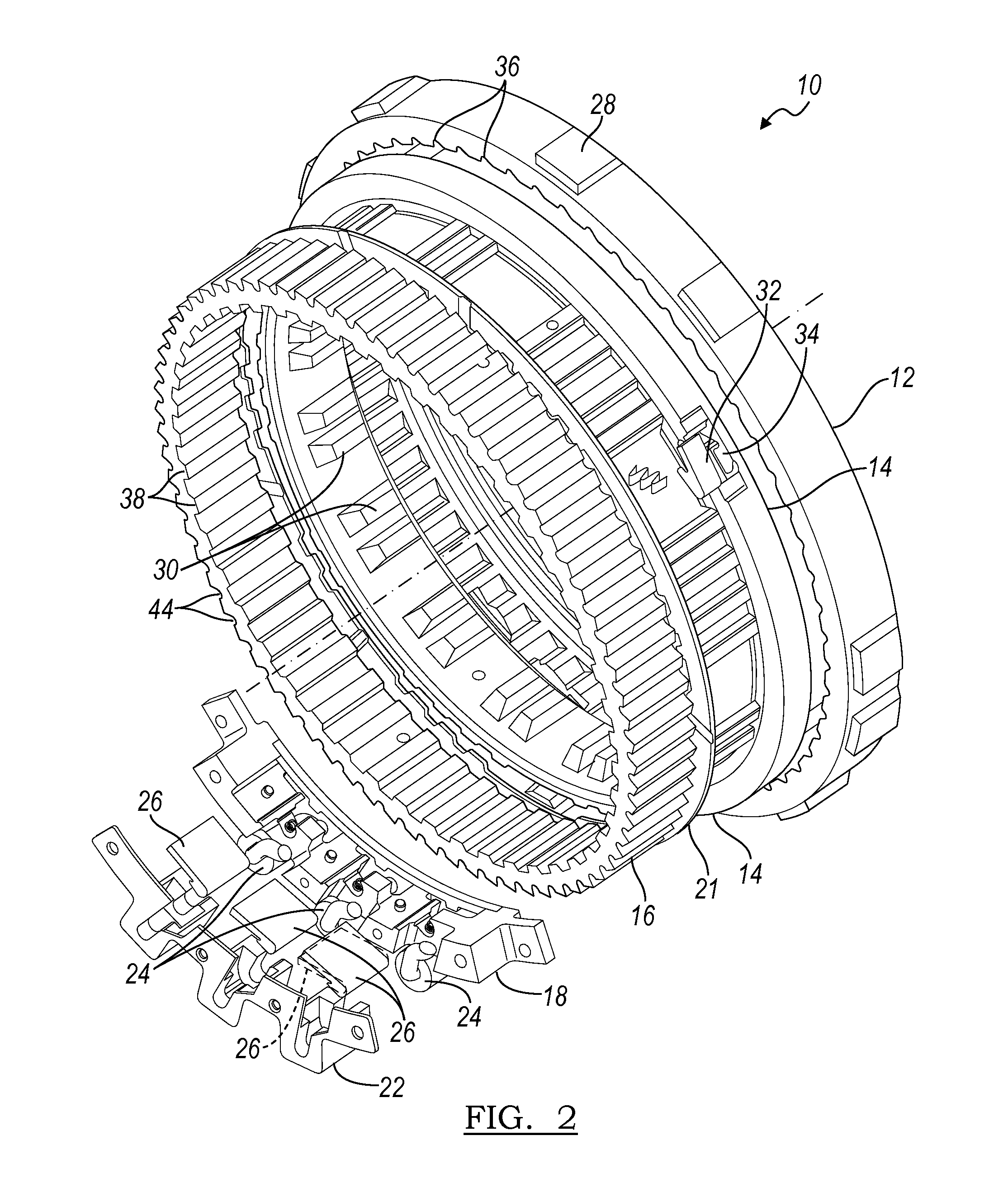
[0017]The selectable OWB 10 shown in FIGS. 1, 2 and 3 includes a radial outer, first cam plate 12; a first pocket plate 14; a radial inner, second cam plate 16; and a radial inner, second pocket plate 18. A lead frame 20 is removed to show three coils 24 of electromagnets and three second struts 26. Plates 12, 14, 16, 18 are aligned with an axis 22.

[0018]The radial outer surface of first cam plate 12 is formed with spline teeth 28, by which cam plate 12 is secured against rotation to a stationary component of a transmission assembly, preferably to a transmission case. Similarly, the radial inner surface of first pocket plate 14 is formed with spline teeth 30, by which pocket plate 14 is secured to a reaction carrier of a transmission gearset. The carrier transmits torque to the OWB 10, causing the first pocket plate 14-second cam plate 16 subassembly to rotate.

[0019]First pocket plate 14 supports struts 32, each strut being urged by a respective spring 34 to pivot radially outward i...


PUM


Abstract

A drive device includes a first one-way coupling including a cam plate, pocket plate and struts, a second one-way coupling including a second cam plate driveably connected to the pocket plate, second pocket plate extending in a partial 5 circular arc and secured to the cam plate, and second struts for opening and closing a drive connection between said second plates, and electromagnets for causing the second struts to close said drive connection.

Description

BACKGROUND OF THE INVENTION[0001]1. Field of the Invention[0002]This invention relates generally to an overrunning, one-way drive device, such as a brake or clutch, whose engaged and disengaged states are selectively controllable.[0003]2. Description of the Prior Art[0004]Conventionally a one-way brake (OWB) or one-way clutch requires two circular rings or raceways, because the raceway that transmits input torque contains the locking elements, such as rollers, struts, or rockers. The input race contains the struts because centrifugal forces are used to move the locking elements away from the output race, which reacts torque. The output raceway is annular, because the locking elements may stop at any location against the output raceway.[0005]Centrifugal force is used to move the locking elements away from the output raceway to limit the duty cycle on the locking elements and springs during the overrun phase of the OWB. If centrifugal force were not employed in this way, the locking e...

Claims


Application Information

Patent Timeline
IPC IPC(8): F16D41/08
CPCF16D27/00F16D41/084F16D41/14
Inventor BIRD, NORMAN J.
Owner FORD GLOBAL TECH LLC
Why Eureka
Try Eureka