Cover assembly and electronic device using the same

a technology of electronic devices and covers, applied in the direction of hinges, electric apparatus casings/cabinets/drawers, instruments, etc., can solve the problems of affecting the beauty of appearance, affecting the size of desktop computers, and affecting the appearance of desktop computers, so as to prevent dust, prevent dust, and maintain the operation stability of electronic devices.

Active Publication Date: 2013-12-05
ASUSTEK COMPUTER INC
View PDF3 Cites 48 Cited by
  • Summary
  • Abstract
  • Description
  • Claims
  • Application Information

AI Technical Summary

Benefits of technology

[0010]As stated above, via the first covering element and the second covering element, the pivot is covered by the cover assembly in rotating. The pivot does not expose from the electronic device to keep wholeness in appearance of the electronic device and prevent dust.
[0011]Moreover, the connecting cable of the electronic device may be disposed between the cover assembly and the pivot to prevent dust and keep operation stability of the electronic device.

Problems solved by technology

However, the desktop computer has a large size, and as technology develops, components of the desktop computer become smaller.
However, the inner structure of the pivot 14 is exposed from the electronic device 1, which affects the beauty in appearance, and dust easily accumulates.
However, a part of the connecting cable 15 still is exposed from the pivot 14, and dust is easy to attach to the connecting cable 15, which affects whole operation of the electronic device 1.

Method used


Image

  • Cover assembly and electronic device using the same
  • Cover assembly and electronic device using the same
  • Cover assembly and electronic device using the same

Examples


first embodiment

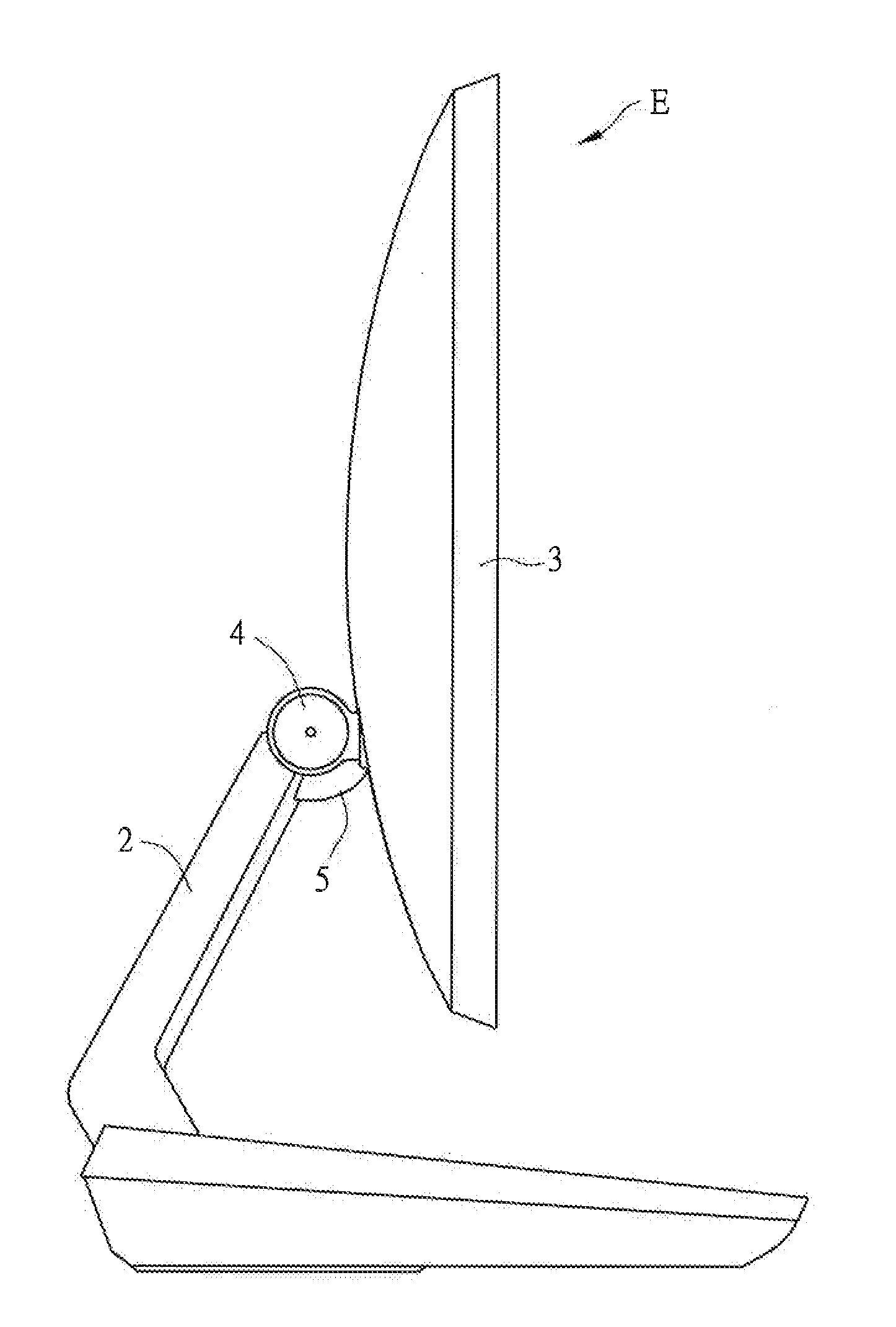
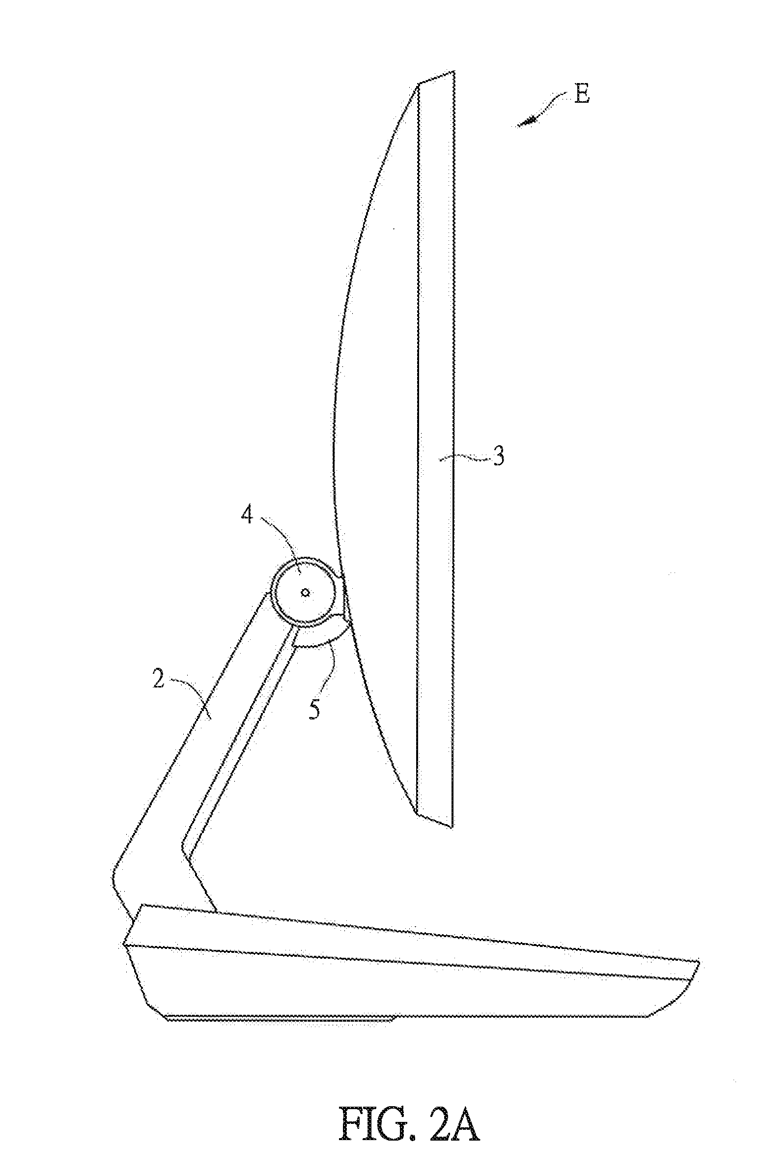
[0021]FIG. 2A is a schematic diagram showing an electronic device in a first embodiment, and FIG. 2B is an enlarged sectional diagram showing a cover assembly in FIG. 2A. Please refer to FIG. 2A and FIG. 2B, an electronic device E includes a first component 2, a second component 3, a pivot 4 and a cover assembly 5. The pivot 4 is connected between the first component 2 and the second component 3 of the electronic device E. The cover assembly 5 can be applied to any electronic device E with the pivot 4. In the embodiment, the electronic device is an integrated electronic device, the first component 2 is a supporting element, and the second component 3 is a tablet display device. The tablet display device may be a touch control tablet display device, which is not limited herein. Thus, the second component 3 (the tablet display device) can rotate relatively to the first component 2 (the supporting element) via the pivot 4, and the cover assembly 5 covers the pivot 4 (as shown in FIG. 3...

second embodiment

[0028]FIG. 4A is an enlarged sectional diagram showing a cover assembly in a second embodiment, and FIG. 4B and FIG. 4C are schematic diagrams showing moving of the cover assembly in FIG. 4A. Please refer to FIG. 4A to FIG. 4C, the cover assembly 5 further includes at least one third covering element 53 to enable the second component 3 to rotate by a larger angle around the pivot 4 (as shown in FIG. 4B to FIG. 4C). The third covering element 53 is disposed between the first covering element 51 and the second covering element 52 (as shown in FIG. 4A).

[0029]The detail symbols are shown in FIG. 4C to keep other figures simple and clean. Please refer to FIG. 4C and FIG. 4A, the third covering element 53 includes a third body 531, a third limit part 532 and a fourth limit part 533. The third limit part 532 is disposed at one end of the third covering element 53, and the fourth limit part 533 is disposed at the other end, which means the third limit part 532 and the fourth limit part 533 ...


PUM


Abstract

A cover assembly for covering a pivot of an electronic device is disclosed. The pivot connects a first component and a second component of the electronic device. The cover assembly is disposed at one side of the pivot, and the cover assembly includes a first covering element and a second covering element. A first end of the first covering element is connected to the first component, and a second end of the first covering element includes a first limit part. A first end of the second covering element is connected to the second component, and a second end of the second covering element includes a second limit part. The first covering element is overlapped with the second covering element. When the pivot rotates, the first limit part and the second limit part move correspondingly.

Description

CROSS-REFERENCE TO RELATED APPLICATION[0001]This application claims the priority benefit of U.S. provisional application Ser. No. 61 / 653,537, filed on May 31, 2012, and Taiwan application serial no. 102113043, filed on Apr. 12, 2013. The entirety of the above-mentioned patent applications are hereby incorporated by reference herein and made a part of specification.BACKGROUND OF THE INVENTION[0002]1. Field of the Invention[0003]The invention relates to a cover assembly and, more particularly, to a cover assembly covering a pivot of an electronic device.[0004]2. Description of the Related Art[0005]As technology develops, requirements of electronic devices, such as a desktop computer or a portable computer, gradually increase. Taking an early desktop computer as an example, a host and a display screen are separate. However, the desktop computer has a large size, and as technology develops, components of the desktop computer become smaller. Thus, an integrated electronic device (which m...

Claims


Application Information

Patent Timeline
Patent Type & Authority Applications(United States)
IPC IPC(8): H05K7/00
CPCH05K7/00G06F1/1681G06F1/1683E05D11/1007E05D11/06E05D11/08E05D11/1028E05D11/0054E05D11/10
Inventor LIU, YU-SEHSIAO, HSIN-HUNG
Owner ASUSTEK COMPUTER INC
Why Eureka
Try Eureka