Hollow Rigid Cam Lock

Inactive Publication Date: 2013-12-05
CONRAD JAMES R
View PDF12 Cites 7 Cited by
  • Summary
  • Abstract
  • Description
  • Claims
  • Application Information

AI Technical Summary

Benefits of technology

[0017]In a further embodiment, the interior of the spindle is shaped so as to prevent the reinforcement ring from becoming disl

Problems solved by technology

Building temporary structures like scaffolding or bridges which allow workers closer proximity to a given task are time consuming and expensive to construct, or are heavy and awkward to transport, and often require additional precautions to use safely.
Frequently, available workspace around task sites cannot easily or safely accommodate a human being, but removal or modification of material to enlarge or make safe a site is rarely viable or economical.
Poles of any sizable length are awkward to transport, which has given rise to design of telescoping or collapsible poles made of concentric cylindrical tubes of varying diameters.
However, existing cam lock designs suffer from several problems.
First, existing designs are prone to b

Method used


Image

  • Hollow Rigid Cam Lock
  • Hollow Rigid Cam Lock
  • Hollow Rigid Cam Lock

Examples


Embodiment Construction

[0025]The following describes preferred embodiments. However, embodiments of the invention are not limited to those embodiments. Therefore, the description that follows is for purpose of illustration and not limitation.

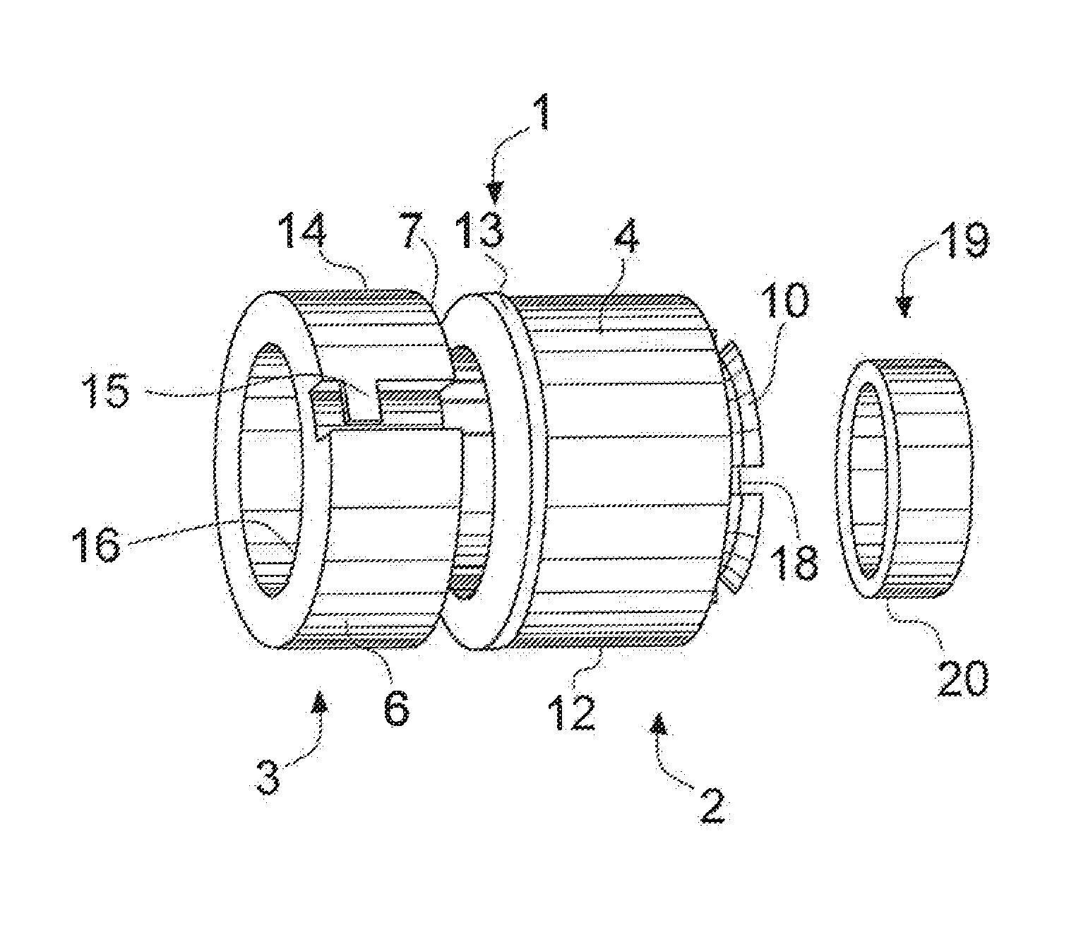
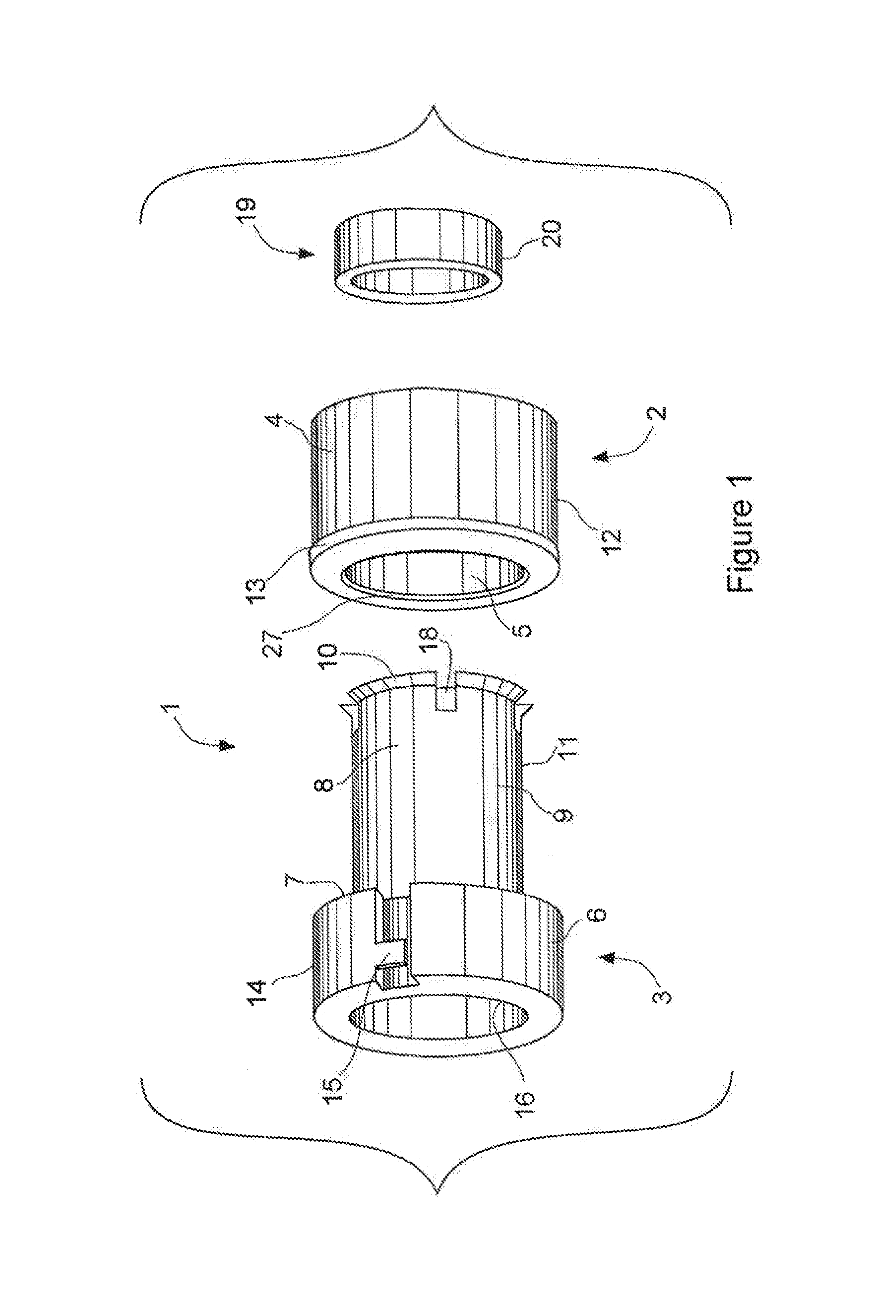
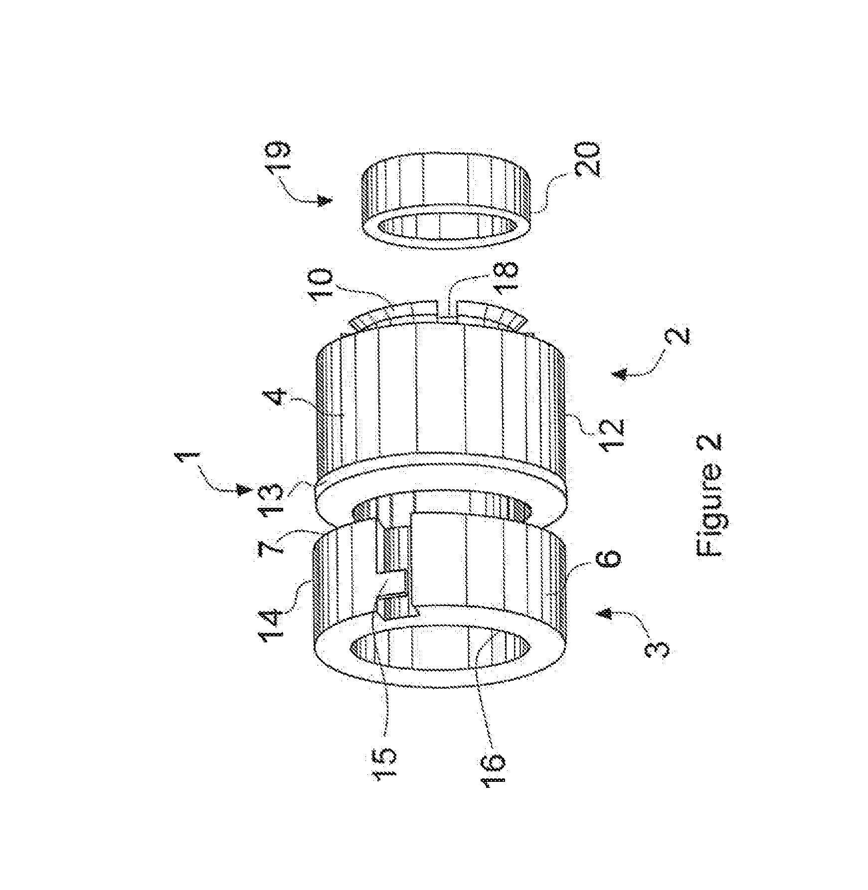
[0026]FIG. 1 depicts an exploded view of the invention cam locking device 1 comprising a female construction 2 and a male construction 3.

[0027]The female construction 2 further comprises a female body 4, a cylindrical spindle cavity 5 centered about a spindle cavity axis 23, and optionally a radial cutaway or countersink 27 on the end of the spindle cavity 5 accommodating the flared end 10 upon entry into the spindle cavity 5. The diameter of the spindle cavity 5 is typically less than that of the flared end 10 and greater than that of the spindle body 9. The spindle cavity axis 23 is offset from the female body center axis 25.

[0028]The male construction 3 further comprises a male body 6, a male body shoulder 7, and a cylindrical spindle 8 protruding from the male bod...


PUM


Abstract

A cam locking device comprising a male construct and a female construct the female construct for installation in a smaller tube, and the male construct for contacting an interior of a larger tube for impermanently fixing the relative position of the smaller and larger tubes.

Description

[0001]This invention allows for two concentric tubes or extrusions (hereafter all referred to as “tubes”) with similar cross sections differing in size to float freely, one inside the other, until the invention is activated at which time the tubes' relative positions become rigidly fixed. The invention may then be deactivated, allowing the tubes to again float freely. The invention may be activated at arbitrary points, and more than one of the invention may be used to join several tubes. Activation and deactivation does not permanently alter or damage the structure of the invention or the tubes.BACKGROUND OF THE INVENTION[0002]Many jobs require the performance of specific tasks in inconvenient locations. Inexhaustive examples include painting a high wall or retrieving debris from the center of a large pool. Building temporary structures like scaffolding or bridges which allow workers closer proximity to a given task are time consuming and expensive to construct, or are heavy and awk...

Claims


Application Information

Patent Timeline
IPC IPC(8): F16B7/14
CPCF16B7/1427F16L27/12Y10T403/32501
Inventor CONRAD, JAMES R.
Owner CONRAD JAMES R
Why Eureka
Try Eureka