Method for refreshing the injection law of a fuel injector

a fuel injector and injection law technology, which is applied in the direction of liquid fuel feeders, machines/engines, electric control, etc., can solve the problems of low error between the normal and the total error of the fuel quantity that is actually injected is significant, and the error between the nominal injection law and the actual injection law may even be very high

Active Publication Date: 2013-12-12
MARELLI EURO SPA
View PDF11 Cites 14 Cited by
  • Summary
  • Abstract
  • Description
  • Claims
  • Application Information

AI Technical Summary

Benefits of technology

[0012]It is an object of the invention to provide a method for refreshing the injection law of a fuel injector, which method is free from the above-described drawbacks and, in particular, easy and cost-effective to implement and allows avoidance in any situation operating irregularities of the internal-combustion engine.

Problems solved by technology

However, it has been observed that replacing a single “long” injection (having a duration equal to the desired actuation time), which occurs in a linear operating zone of the fuel, with many consecutive “short” injections (each of which feeds a fuel quantity equal to a sub-multiple of the desired fuel quantity), which occurs in a ballistic operating zone of the fuel injector, may lead to a significant total error of the fuel quantity that is actually injected (i.e., the fuel quantity that is actually injected by the series of “short” injections can be significantly different from the desired fuel quantity) because the injection errors of all the consecutive “short” injections are algebraically summed.
In other words, the error between the normal injection law and the actual injection law is always low when the fuel injector is used in the linear operating zone whereas the error between the nominal injection law and the actual injection law may be even very high when the fuel injector is used in the ballistic operating zone.
Above all, at the beginning of the actual injection law of each fuel injector, the actual behavior of the fuel injector in the ballistic operating zone is not known with adequate accuracy.
Thus, replacing single operation in the linear operating zone with multiple operation in the ballistic operating zone may imply very high errors in the injected-fuel quantity with major repercussions on the operating smoothness of the internal-combustion engine.

Method used


Image

  • Method for refreshing the injection law of a fuel injector
  • Method for refreshing the injection law of a fuel injector
  • Method for refreshing the injection law of a fuel injector

Examples


Embodiment Construction

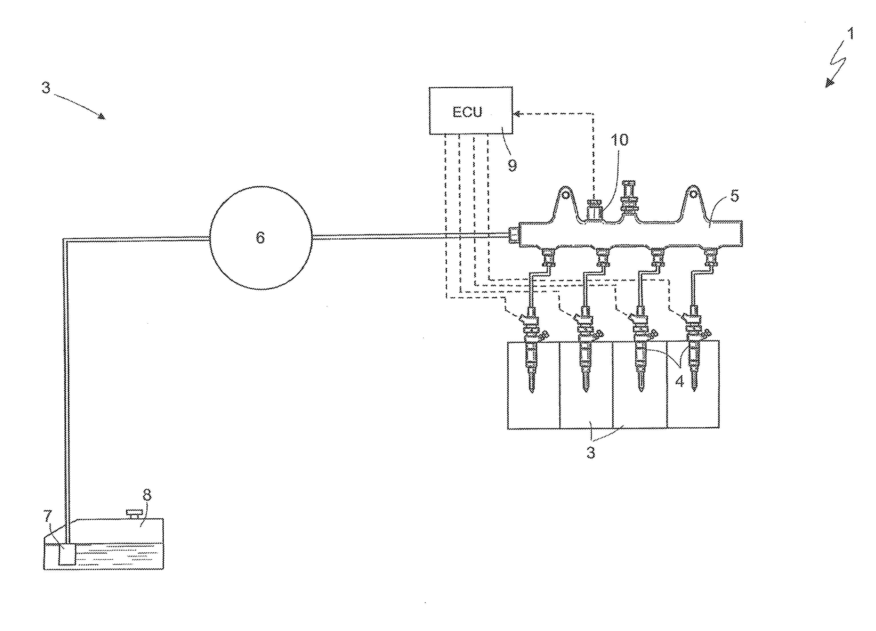
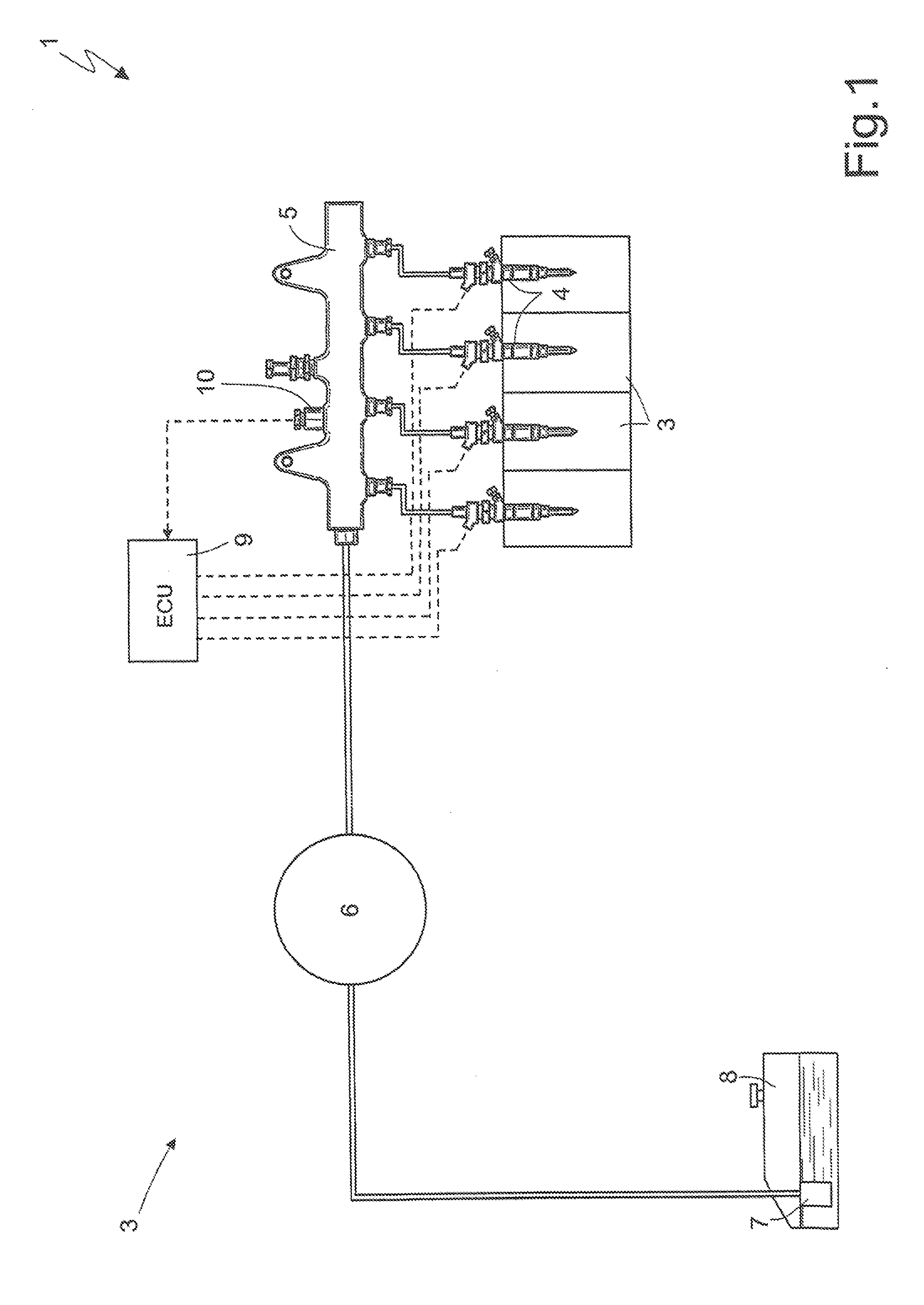
[0017]In FIG. 1, an internal-combustion engine is generally indicated at 1 and provided with four cylinders 2 and a common rail-type injection system 3 for direct injection of fuel into the cylinders 2 themselves. The injection system 3 includes four electromagnetic fuel injectors 4 each of which injects fuel directly into a respective cylinder 2 of the engine 1 and receives pressurized fuel from a common rail 5 (for example, each fuel injector 4 is made as described in Patent Application EP2455605A1). The injection system 3 includes a high-pressure pump 6, which feeds fuel to the common rail 5 and is actuated directly by a driving shaft of the internal-combustion engine 1 by a mechanical transmission the actuation frequency of which is directly proportional to the rotation speed of the driving shaft. In turn, the high-pressure pump 6 is fed by a low-pressure pump 7 arranged within the fuel tank 8.

[0018]Each fuel injector 4 injects a variable fuel quantity into the corresponding cyl...


PUM


Abstract

A method refreshes an injection law of a fuel injector to be tested in an injection system. The method comprises steps of establishing a desired fuel quantity for the fuel injector to be tested, performing at least one first measurement opening of the fuel injector to be tested in a test actuation time, determining a pressure drop in a common rail during the first measurement opening of the fuel injector to be tested, determining a first fuel quantity that is fed during the first measurement opening, calculating a second fuel quantity as a difference between the desired fuel quantity and the first fuel quantity, and performing a second completion opening of the fuel injector to be tested for feeding the second fuel quantity needed to reach the desired fuel quantity.

Description

REFERENCE TO RELATED APPLICATION[0001]This application is based upon and claims priority to Italian Patent Application BO2012A 000310 filed on Jun. 6, 2012.BACKGROUND OF INVENTION[0002]1. Field of Invention[0003]The invention relates to a method for refreshing the injection law of a fuel injector [i.e., for refreshing the law that binds the actuation time (i.e., the driving time) to the injected-fuel quantity].[0004]2. Description of Related Art[0005]Patent Application EP2455605A1 suggests a method for determining the actual injection law of a fuel injector to be tested. The method includes the steps of: interrupting the feeding of fuel from the fuel pump to a common rail; avoiding the opening of all fuel injectors, except for the fuel injector to be tested; measuring the initial fuel pressure inside the common rail before starting the opening of the fuel injector to be tested; opening the fuel injector to be tested for a number of consecutive openings greater than one with a same t...

Claims


Application Information

Patent Timeline
Patent Type & Authority Applications(United States)
IPC IPC(8): F02M69/50
CPCF02M69/50F02D41/2467F02D41/247F02D41/402F02D2200/0602F02D2200/0616F02B2075/1808
Inventor SGATTI, STEFANOPAROTTO, MARCOSERRA, GABRIELESENSI, FABIO
Owner MARELLI EURO SPA
Why Eureka
Try Eureka