Kinetic heat sink having controllable thermal gap

a heat sink and controllable technology, applied in the direction of semiconductor/solid-state device details, lighting and heating apparatus, laminated elements, etc., can solve the problems of energy loss, undesired sealing problems, and waste heat generation of electric circuits and devices

Inactive Publication Date: 2013-12-12
COOICHIP TECH INC
View PDF7 Cites 26 Cited by
  • Summary
  • Abstract
  • Description
  • Claims
  • Application Information

AI Technical Summary

Benefits of technology

[0019]The method may include varying the rotation of the rotating structure, inclu

Problems solved by technology

During operation, electric circuits and devices generate waste heat.
These designs undesirably often have problems relating to sealing, risk of leaks, or high frictional energy losses.
Although air is generally considered a thermal insulator (i.e., not an efficient thermal transfer medium), when the fluid gap is made sufficiently small (i.e., in the order of tens of micrometers), the thermal resis

Method used


Image

  • Kinetic heat sink having controllable thermal gap
  • Kinetic heat sink having controllable thermal gap
  • Kinetic heat sink having controllable thermal gap

Examples


Embodiment Construction

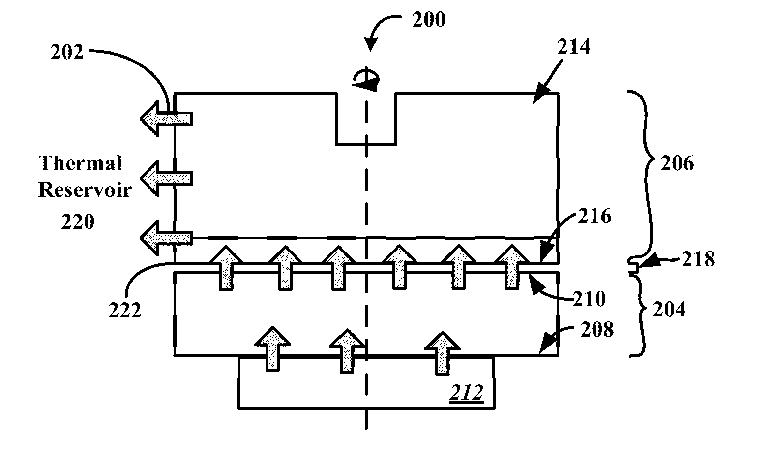
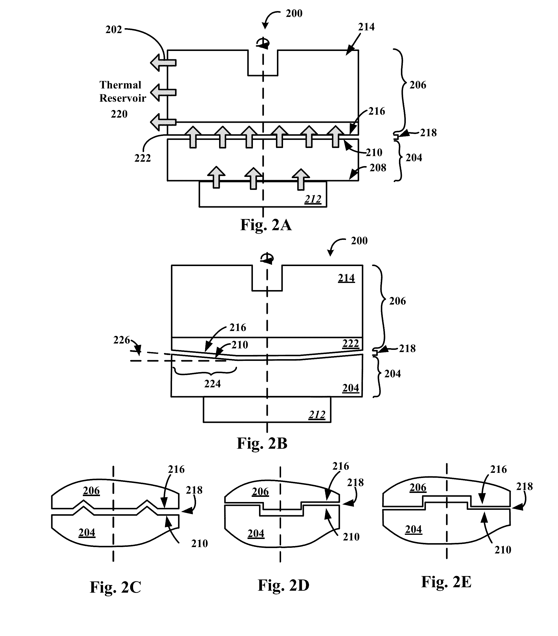
[0006]In accordance with illustrative embodiments of the invention, a kinetic heat sink apparatus has a stationary member that includes a base structure having both a first heat-conducting surface and a second heat-conducting surface to conduct heat therebetween. The first heat-conducting surface is fixably mountable to a heat-generating component. The kinetic heat sink also has a rotating structure rotatably coupled with the base structure. This rotating structure has a movable heat-extraction surface facing the second heat-conducting surface across a spatial gap. The rotating structure is configured to transfer heat from the second heat-conducting surface to a thermal reservoir communicating with the rotating structure. The rotating structure and stationary member has at least two pairs of opposing surfaces configured to form a first thrust and second opposing thrust to maintain the spatial gap within a pre-specified range during rotation of the rotating structure. At least one su...


PUM

PropertyMeasurementUnit
Lengthaaaaaaaaaa
Lengthaaaaaaaaaa
Speedaaaaaaaaaa

Abstract

An apparatus and method for cooling a heat-generating component includes a stationary base structure and a rotating structure. The stationary base structure is mountable at the first heat-conducting surface to or near the heat-generating component. The stationary base structure has a first and second heat-conducting surface to conduct heat therebetween. The rotating structure is rotatably coupled to the stationary base structure. The rotating structure has a heat-extraction surface facing the second heat-conducting surface across a spatial gap. As a result of the rotating structure rotatably moving, the rotating structure substantially transfers the heat from the second heat-conducting surface to a thermal reservoir communicating with the rotating structure. In addition, as a result of the rotating structure rotatably moving, at least two surfaces of the rotating structure and/or the stationary base structure generate a thrust and an opposing thrust to vary and/or maintain the spatial gap.

Description

RELATED APPLICATION[0001]This patent application claims priority from Provisional Application No. 61 / 656,868, filed Jun. 7, 2012, titled “Kinetic Heat Sink Having Controllable Thermal Gap.” The application is incorporated by reference herein in its entirety.TECHNICAL FIELD[0002]The present invention relates to heat-extraction and dissipation devices and methods and, more particularly, kinetic heat sinks for use with electronic components.BACKGROUND ART[0003]During operation, electric circuits and devices generate waste heat. To operate properly, the temperature of the electric circuits and devices has to be within a certain limit. The temperature of an electric device often is regulated using a heat sink physically mounted near or to the electric device. FIGS. 1A, 1B, and 1C show several examples of conventional heat sink assemblies 100. The heat sink assemblies 100 generally extract heat 102 (see FIG. 1C) from the thermal source 104 (i.e., the electric circuit or device) to a heat ...

Claims


Application Information

Patent Timeline
IPC IPC(8): F28F3/00
CPCF28F3/00F28F13/125H01L23/467F28D2021/0029H01L2924/0002H01L2924/00
Inventor GONZALEZ, LINO A.SANCHEZ, WILLIAM R.STODDARD, STEVEN
Owner COOICHIP TECH INC
Why Eureka
Try Eureka