Attitude and Configuration Indicator Display System and Method

a display system and display system technology, applied in surveying and navigation, instruments, navigation instruments, etc., can solve problems such as pilots not arming the automatic ground spoiler system, misapprehension of the configuration status, and pilots not knowing the position of the spoiler, so as to ensure the accuracy of the configuration

Inactive Publication Date: 2013-12-12
VANHOOZER RUSSELL ALAN
View PDF2 Cites 3 Cited by
  • Summary
  • Abstract
  • Description
  • Claims
  • Application Information

AI Technical Summary

Benefits of technology

[0011]The present invention is most generally, an Attitude and Configuration Indicator Display System and Method as part of an Electronic Instrument Display that includes graphical symbol groups representative of the piloted craft's configuration, i.e., including but not limited to the instant positional status of the lift inducing and drag inducing elements. In commercial aircraft, the elements typically comprising the configuration are considered the flaps, the slats, the landing gear, and the spoilers. Configuration should be understood to embody information regarding the deployment, non-deployment, and functioning of these elements either singly or collectively. More specifically, dedicated sensors associated with each configuration element provide the information via a computerized control system in which the symbol groups representative of the configuration elements are integrally displayed within, or proximate to an aircraft reference symbol, which for exemplary purposes only is depicted herein as a chevron symbol occupying the central position within an attitude indicator display. Even more specifically, the configuration elements are represented as symbol groups and are differentiated from one another by at least position, shape, behavior, and furthermore, move in concert with the aircraft reference symbol. The present invention makes it possible for the pilot(s) to view and readily apprehend the aircraft's configuration at a single glance directed to the attitude indicator.
[0012]One object of the present invention is to provide a means to quickly apprehend the configuration status of a piloted craft.
[0013]Another object of the present invention is to help prevent accidents caused by the misapprehension of a piloted craft's configuration during all phases of flight including take-off and landing.
[0014]Yet another object of the present invention is to reduce the number of displays required to apprehend the configuration settings of an aircraft.
[0015]A further object of the present invention is to help reduce mental fatigue due to the concentration required to monitor multiple flight indicators especially in stressful situations.

Problems solved by technology

The misapprehension of the configuration status, and in particular the position of the spoilers figures in a number of recent accidents.
While on most modern transport craft ground spoilers extend automatically upon touchdown, any failure to deploy spoilers in a timely fashion may result in accidents.
The NTSB investigation found that the pilots failed to arm the automatic ground spoiler system.
It was revealed that the spoilers had not deployed and that only one engine had deployed its thrust reverser causing the aircraft to careen off the runway.
In some cases, failure to deactivate the spoilers when accelerating has caused accidents.
For example, failure to deactivate the spoilers while climbing to avoid a mountain contributed to the crash of American Airlines Flight 965 on Dec. 20, 1995.

Method used


Image

  • Attitude and Configuration Indicator Display System and Method
  • Attitude and Configuration Indicator Display System and Method
  • Attitude and Configuration Indicator Display System and Method

Examples


Embodiment Construction

Reference Listing

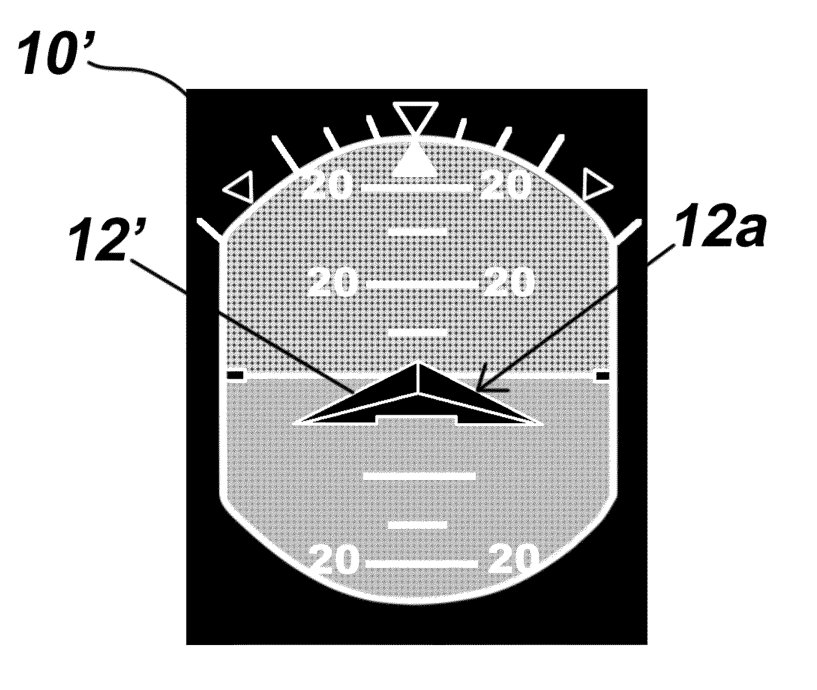
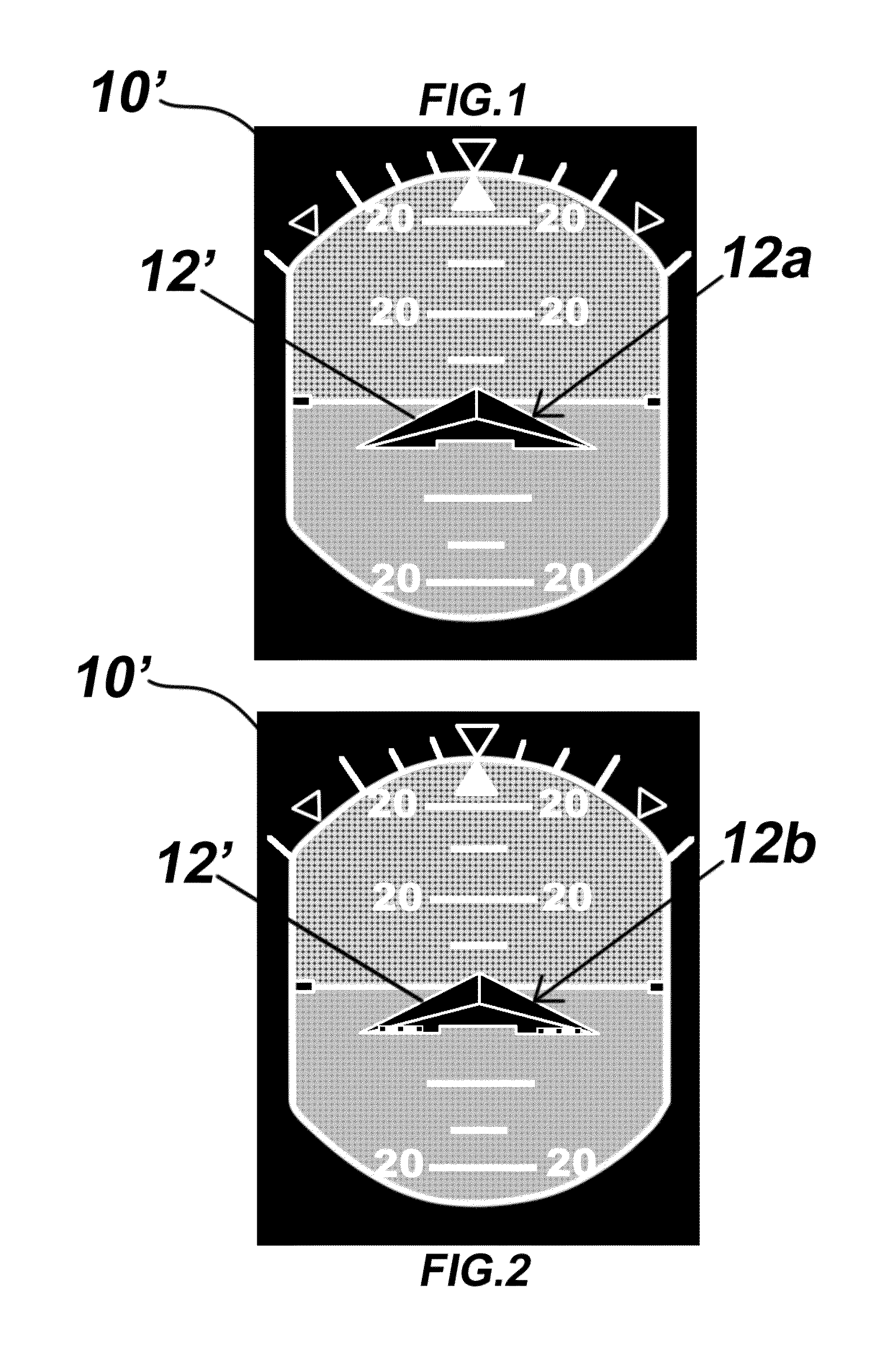
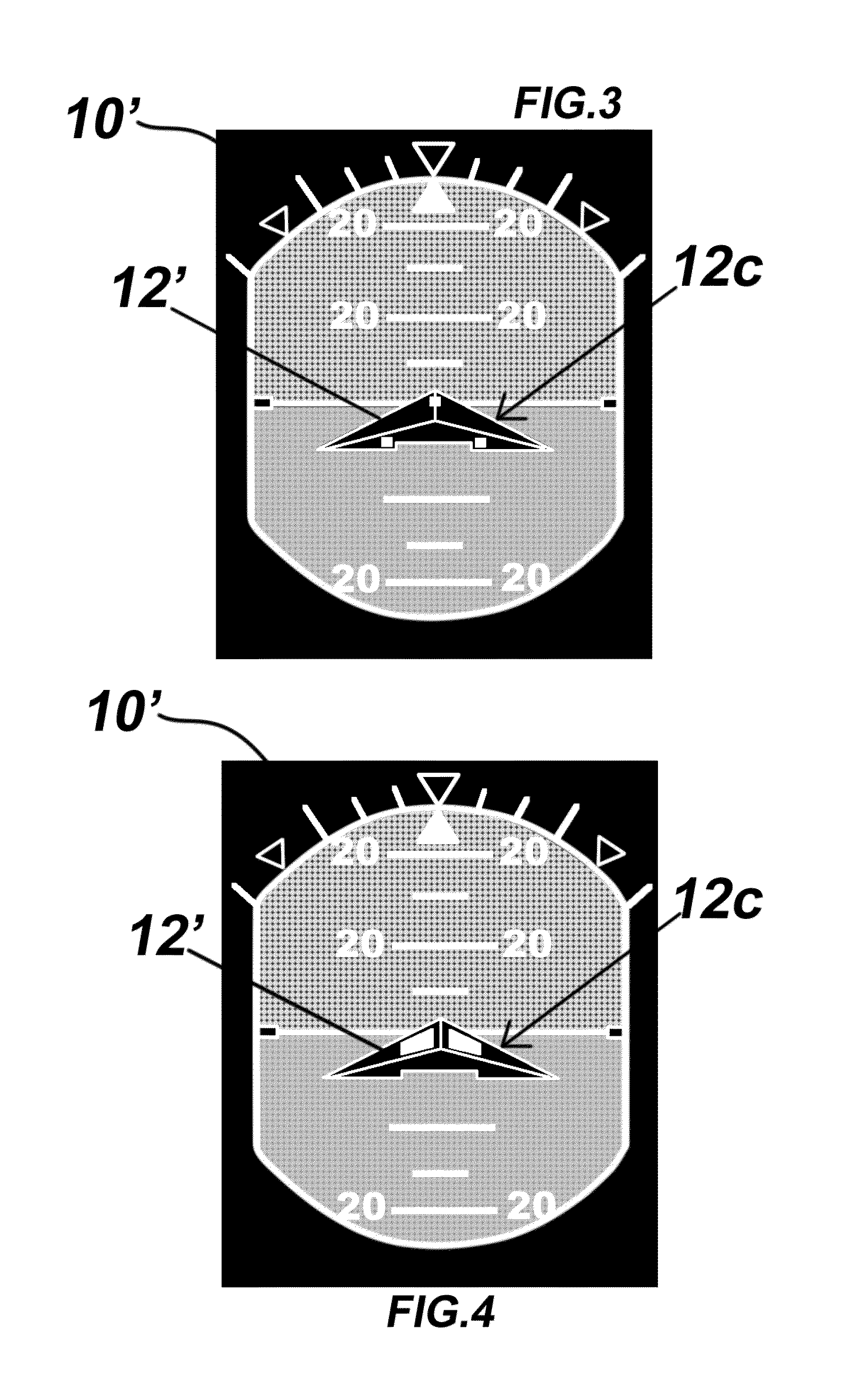
[0032]10′ enhanced attitude indicator[0033]12 aircraft reference symbol[0034]14 flap symbols[0035]14a flap position indicator[0036]14b flap position indicator[0037]14c flap position indicator[0038]16 landing gear symbols[0039]18 spoiler symbols[0040]20 reverse thruster symbol[0041]22 slat symbols

[0042]Referring generally to FIGS. 1-15, an embodiment according to the present invention includes an attitude indicator 10′, and a parent icon 12 shown here typically as a chevron which represents a piloted craft. The particular shape of the parent icon presented herein is merely exemplary and should be considered non-limiting. It should also be understood that while there are many variants of attitude indicators of different design possessing an icon different from the chevron shape depicted and having shapes, colors, borders and proportions that vary, all possess a central icon that at a minimum depicts the wings and nose of the aircraft in relationship to an artificial h...


PUM


Abstract

Attitude and Configuration Indicator Display System and Method within the context of an Electronic Instrument System in which the configuration status of a piloted craft; typically the instant positions of lift inducing elements and drag inducing elements, are represented by symbol groupings integrated with an a parent icon, typically a chevron-type symbol representative of the piloted craft. The symbol groupings receive data from associated on-board sensors and are displayed singly or in combination with each other anytime the piloted craft is not in a clean configuration to instantly alert the pilot(s) of the configuration status with a single glance directed to the attitude indicator.

Description

CROSS REFERENCE TO RELATED APPLICATIONS[0001]This Application is a Continuation Application of U.S. patent application Ser. No. 12 / 661,784 filed Mar. 24, 2010.FIELD OF THE INVENTION[0002]The invention relates generally to electronic instrument display systems and specifically to the display of configuration settings of a piloted craft within an attitude indicator; the piloted craft, including but not limited to, fixed wing aircraft, rotor-wing aircraft, spacecraft, lighter than air aircraft, and watercraft such as ships, barges, boats, semi-submersibles and fully submersible craft.BACKGROUND OF THE INVENTION[0003]Various advances electronic instrument display systems and in particular Electronic Flight Information Systems (EFIS), have been implemented to make the difficult task of interpreting the operational status of commercial aircraft easier for pilots. Generally flight display systems include a primary flight display (PFD) installed in front of the left seat pilot position and ...

Claims


Application Information

Patent Timeline
Patent Type & Authority Applications(United States)
IPC IPC(8): B64D45/00
CPCB64D45/00G01C23/005
Inventor VANHOOZER, RUSSELL ALANWILBURN, BRADLEY G.
Owner VANHOOZER RUSSELL ALAN
Why Eureka
Try Eureka