Light diffusion member, method of manufacturing same, and display device

a technology of light diffusion and manufacturing methods, applied in the field of light diffusion members, can solve the problems of narrow viewing angle, and achieve the effect of widening the viewing angle and good display quality

Active Publication Date: 2013-12-12
SHARP KK
View PDF6 Cites 48 Cited by
  • Summary
  • Abstract
  • Description
  • Claims
  • Application Information

AI Technical Summary

Benefits of technology

[0024]With the embodiments of the present invention, the light diffusion member and the method of manufacturing the same can be obtained which is able to widen the viewing angle by making light diffused in various directions. Furthermore, with the embodiments of the present invention, the display device can be obtained which includes the light diffusion member and has good display quality.

Problems solved by technology

However, it is generally known so far that a liquid crystal display device has good viewability when looked from the front side, but its viewing angle is narrow.

Method used


Image

  • Light diffusion member, method of manufacturing same, and display device
  • Light diffusion member, method of manufacturing same, and display device
  • Light diffusion member, method of manufacturing same, and display device

Examples


first embodiment

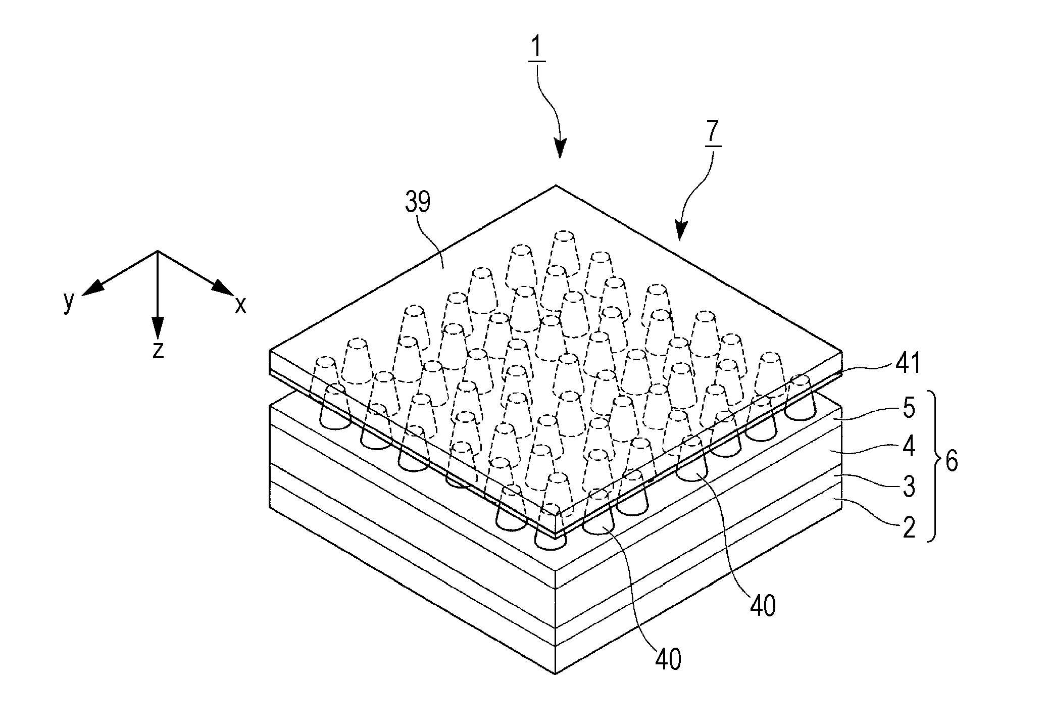
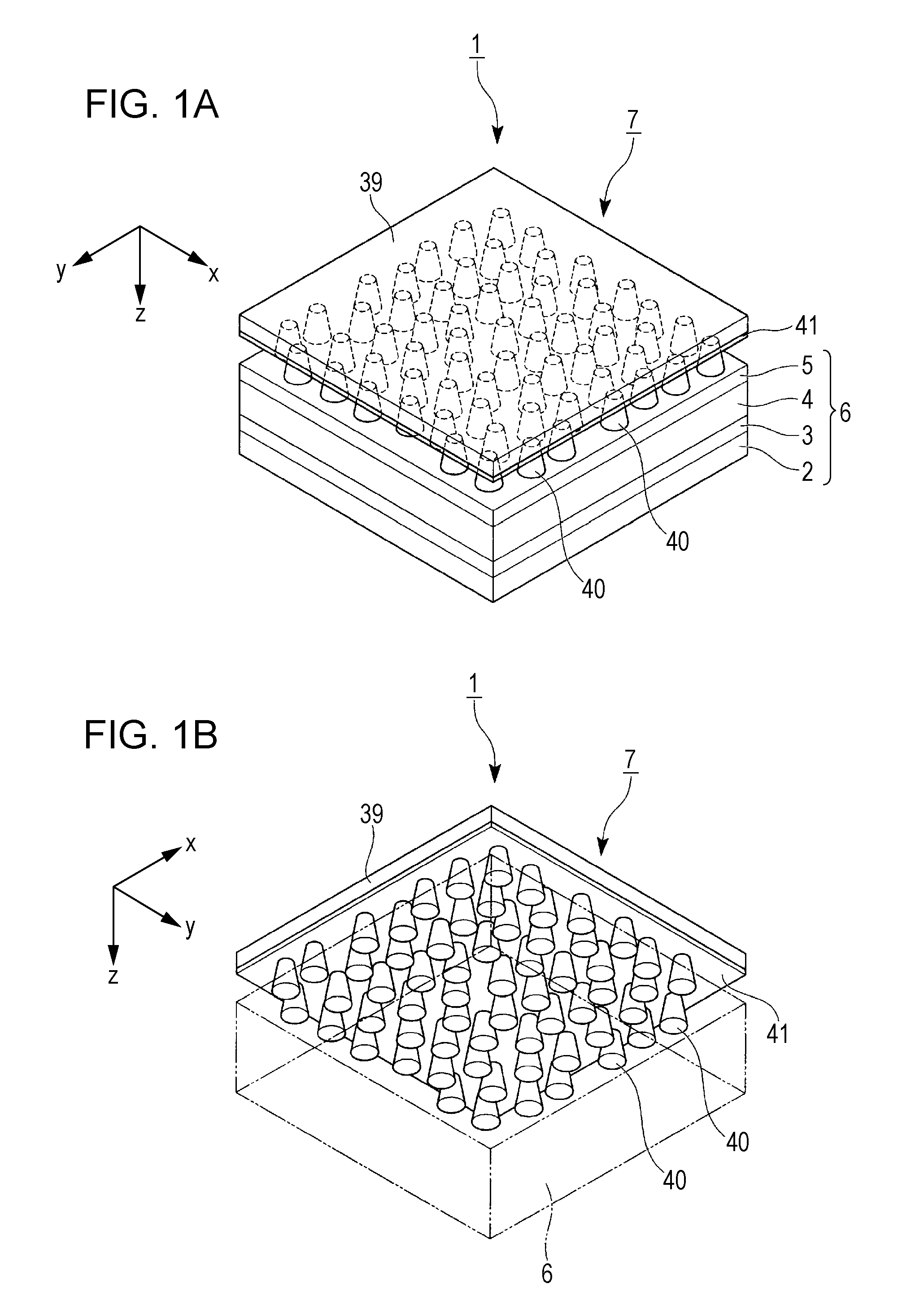
[0061]A first embodiment of the present invention will be described below with reference to FIGS. 1A to 13.

[0062]The first embodiment is described in connection with an example of a liquid crystal display device that includes a transmission type liquid crystal panel as a display main unit.

[0063]It is to be noted that, in all of the drawings referred to in the following, dimension scales may be set different depending on constituent elements for easier understanding of the constituent elements in appearance.

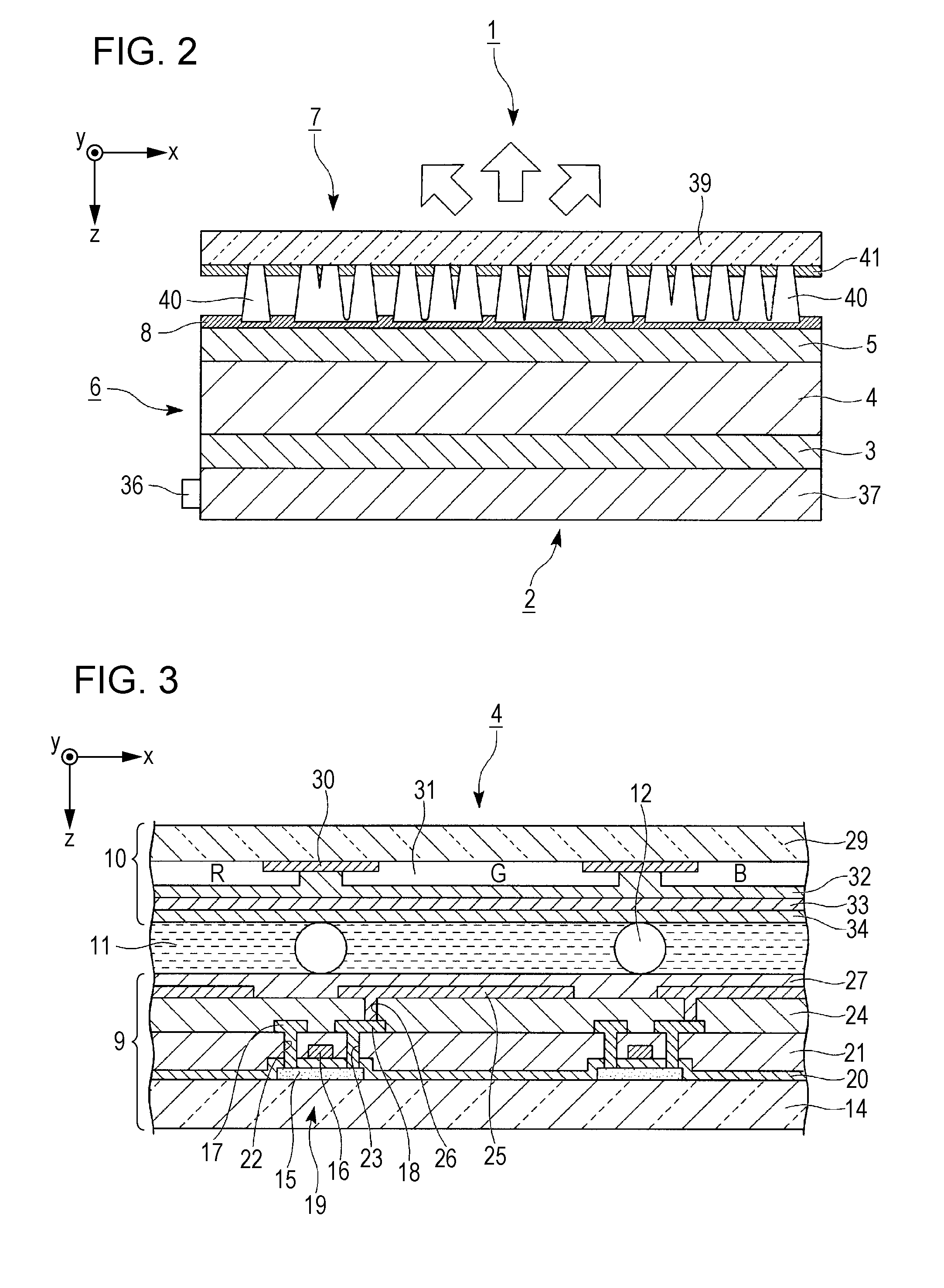
[0064]FIG. 1A is a perspective view of the liquid crystal display device according to the first embodiment when looked from a point obliquely upward away from the liquid crystal display device (i.e., from the viewing side). FIG. 1B is a perspective view of the liquid crystal display device according to the first embodiment when looked from a point obliquely downward away from the liquid crystal display device (i.e., from the rear surface side). FIG. 2 is a vertical sectional view ...

second embodiment

[0129]A second embodiment of the present invention will be described below with reference to FIGS. 14 to 16B.

[0130]A basic structure of a liquid crystal display device according to the second embodiment is the same as that in the first embodiment, and the second embodiment is different from the first embodiment in shapes of light diffusion portions of a viewing-angle widening film. In the second embodiment, therefore, description of the basic structure of the liquid crystal display device is omitted and only the viewing-angle widening film is described.

[0131]FIG. 14 is a vertical sectional view of the liquid crystal display device according to the second embodiment. FIG. 15A is a vertical sectional view of the viewing-angle widening film according to the second embodiment. FIG. 15B is a plan view of a photomask that is used in manufacturing the viewing-angle widening film. FIGS. 16A and 16B are illustrations to explain a method of manufacturing the viewing-angle widening film accord...

third embodiment

[0141]A third embodiment of the present invention will be described below with reference to FIGS. 17 and 18.

[0142]A basic structure of a liquid crystal display device according to the third embodiment is the same as that in the first embodiment, and the third embodiment is different from the first embodiment in shapes of light diffusion portions of a viewing-angle widening film. In the third embodiment, therefore, description of the basic structure of the liquid crystal display device is omitted and only the viewing-angle widening film is described.

[0143]FIG. 17 is a vertical sectional view of the liquid crystal display device according to the third embodiment. FIG. 18 is a vertical sectional view of the viewing-angle widening film according to the third embodiment.

[0144]It is to be noted that, in FIGS. 17 and 18, constituent elements common to those in the drawings referred to in the first embodiment are denoted by the same signs and detailed description of those constituent elemen...


PUM


Abstract

A light diffusion member includes a light-transmissive base, a plurality of light diffusion portions, a connecting portion, and a light absorbing layer. The light diffusion portions are arranged on one surface of the base and have light-incident end surfaces each positioned on the side away from the base and having a larger area than a light-emergent end surface thereof. The connecting portion connects at least two adjacent ones of the plural light diffusion portions to each other, and is positioned near the light-incident end surfaces of the adjacent light diffusion portions. The light absorbing layer is formed on the one surface of the base in a region different from a region where the light diffusion portions are formed. A size from the light-incident end surface to the light-emergent end surface of the light diffusion portion is larger than a thickness of the light absorbing layer.

Description

TECHNICAL FIELD[0001]The present invention relates to a light diffusion member, a method of manufacturing the same, and a display device.[0002]The present application claims priority on the basis of Japanese Patent Application No. 2011-046262, filed in the Japan Patent Office on Mar. 3, 2011, the entire contents of which are incorporated herein by reference.BACKGROUND ART[0003]Liquid crystal display devices are widely used as displays of portable electronic devices including cellular phones, or of televisions, personal computers, and so on. However, it is generally known so far that a liquid crystal display device has good viewability when looked from the front side, but its viewing angle is narrow. For that reason, various ideas have been proposed to widen the viewing angle. One of those ideas is to dispose a member (hereinafter referred to as a “light diffusion member”) for diffusing light emerging from a display main unit, including a liquid crystal panel, etc., on the viewing si...

Claims


Application Information

Patent Timeline
Patent Type & Authority Applications(United States)
IPC IPC(8): F21V13/12F21V13/02
CPCF21V13/12F21V13/02G02B5/0247G02F1/133504G02F1/133562
Inventor YAMAMOTO, EMIKANNO, TORUMAEDA, TSUYOSHI
Owner SHARP KK
Why Eureka
Try Eureka