Screw post

a screw and post technology, applied in the field of screw posts, can solve the problems of increasing the manufacturing cost of screw posts, screw posts could receive considerable circumferential stress, screw posts may crack accordingly,

Active Publication Date: 2013-12-12
WISTRON CORP
View PDF18 Cites 9 Cited by
  • Summary
  • Abstract
  • Description
  • Claims
  • Application Information

AI Technical Summary

Problems solved by technology

Thus, the screw post could receive a considerable circumferential stress.
When the aforesaid circumferential stress is excessive, the screw post may crack accordingly.
However, all the aforesaid designs may increase the manufacturing cost of the screw post.
However, this design may also increase the manufacturing cost of the screw post 10.
Furthermore, this design...

Method used


Image

  • Screw post
  • Screw post
  • Screw post

Examples


Embodiment Construction

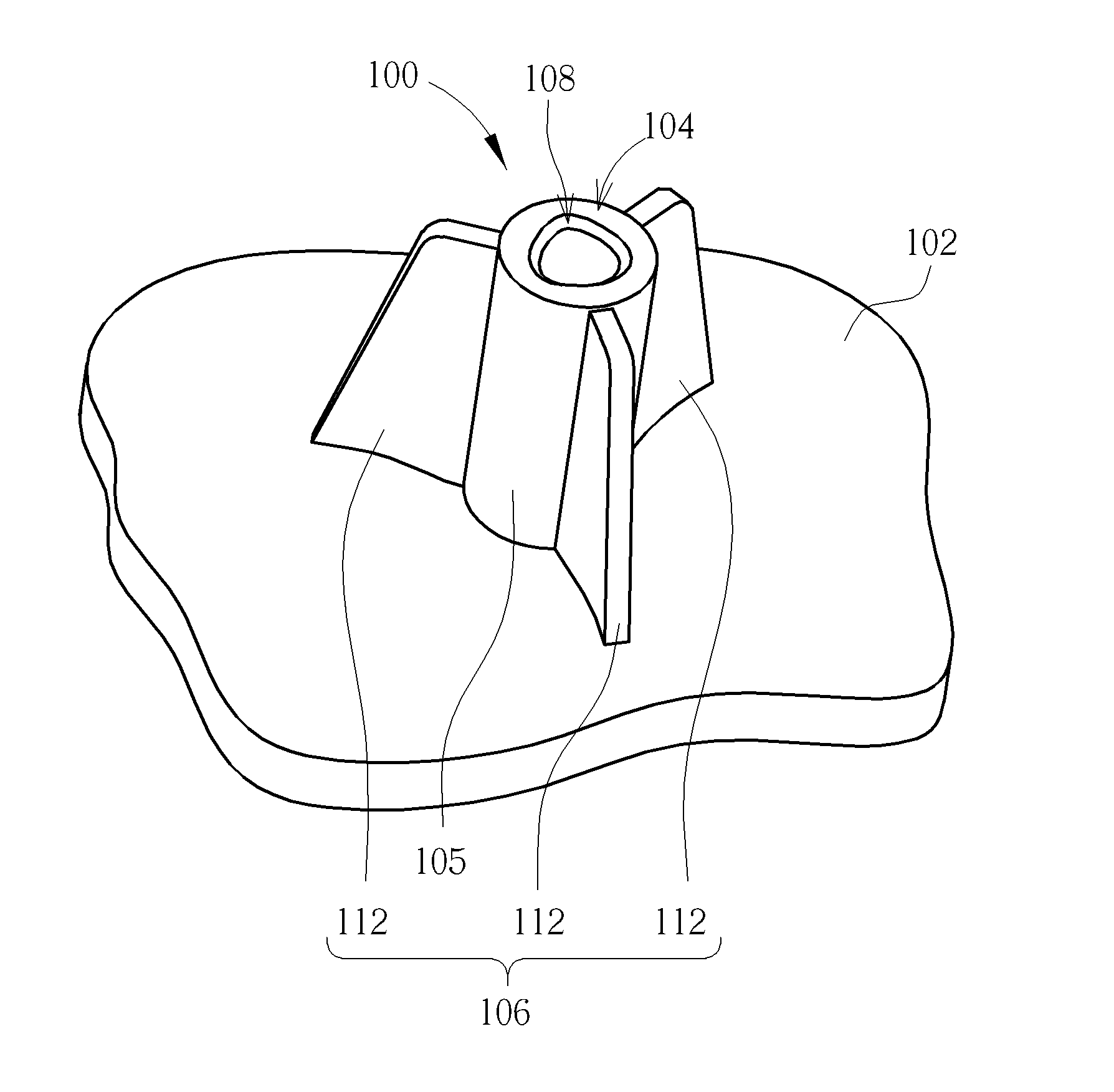
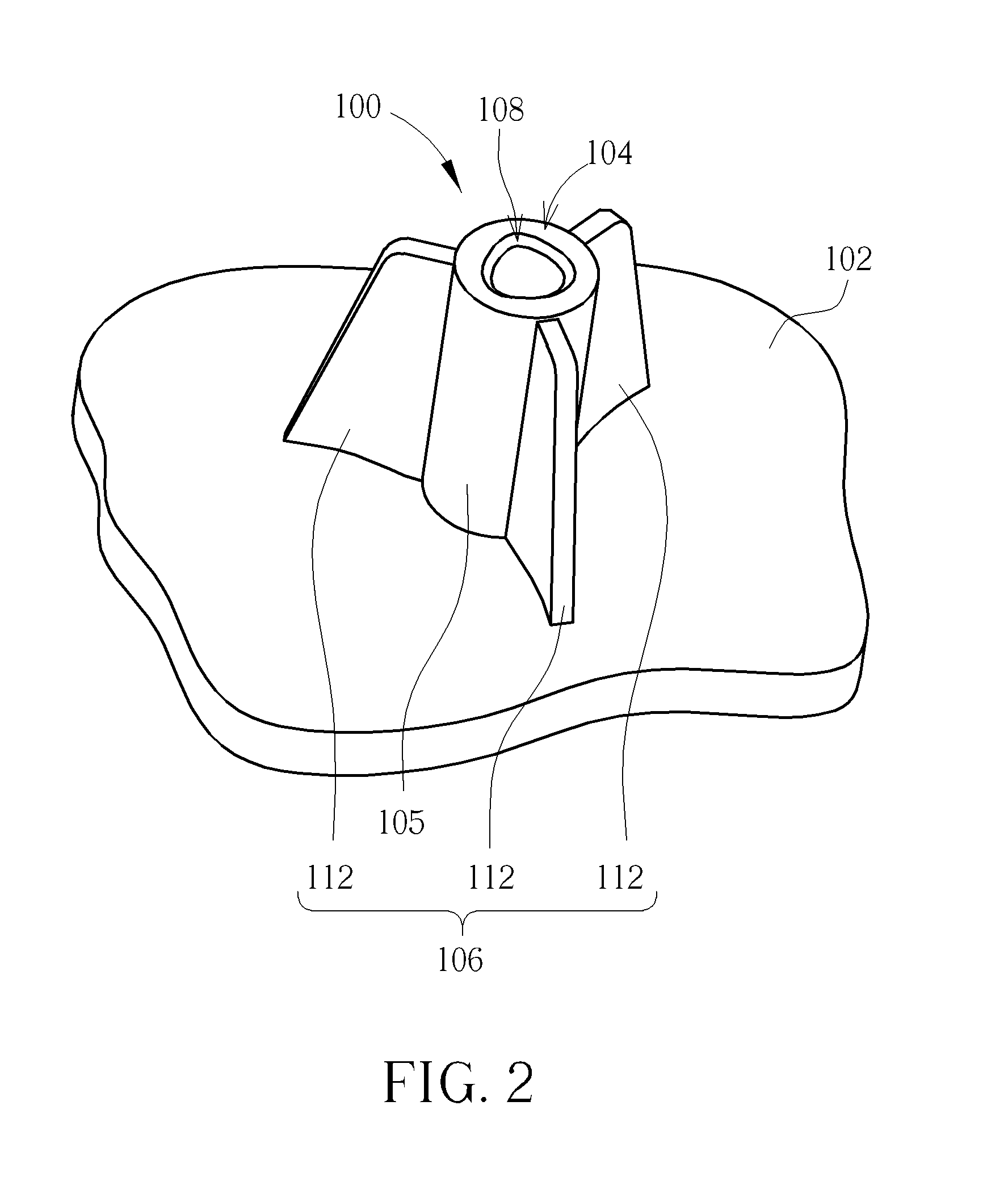
[0018]Please refer to FIG. 2 and FIG. 3. FIG. 2 is a diagram of a screw post 100 according to an embodiment of the invention. FIG. 3 is a top view of the screw post 100 in FIG. 2. In this embodiment, the screw post 100 could be integrally formed with a plate 102 (e.g. a plastic plate) for screwing with a self-tapping screw (e.g. a standard self-tapping screw, a self-tapping screw with cutting openings, or a self-tapping screw having an approximately triangular section) so as to cooperatively fix an object (e.g. a plastic part) onto the plate 102, but is not limited thereto. That is to say, the screw post 100 could also be an independent part instead to be detachably disposed on the plate 102. As for which design is utilized, it depends on the practical application of the screw post 100.

[0019]More detailed description for the structural design of the screw post 100 is provided as follows. As shown in FIG. 2 and FIG. 3, the screw post 100 includes a post body 104 and a rib structure 1...


PUM


Abstract

A screw post is detachably screwed with a self-tapping screw. The screw post includes a post body and a rib structure. The post body has an approximately triangular hollow structure formed therein. The approximately triangular hollow structure has three arc-shaped sides. The rib structure protrudes from an outer surface of the post body corresponding to at least one of the three arc-shaped sides in an axially-extending manner. The self-tapping screw is screwed into the approximately triangular hollow structure.

Description

BACKGROUND OF THE INVENTION[0001]1. Field of the Invention[0002]The present invention relates to a screw post, and more specifically, to a screw post utilizing cooperating of an approximately triangular hollow structure formed therein with reinforcement ribs for preventing itself from cracking.[0003]2. Description of the Prior Art[0004]In general, a self-tapping screw utilizes its positive threads to generate corresponding negative threads on an inner wall of a screw hole so as to be screwed into the screw hole tightly. Chips cut by the positive threads of the self-tapping screw may clog up between the positive threads and the negative threads so as to apply a radial pushing force upon the screw post. Thus, the screw post could receive a considerable circumferential stress. When the aforesaid circumferential stress is excessive, the screw post may crack accordingly.[0005]For solving the aforesaid problem, a crack preventing design could be applied to the self-tapping screw. For exam...

Claims


Application Information

Patent Timeline
IPC IPC(8): F16B29/00
CPCF16B37/005
Inventor CHEN, DONG-YINGMAO, ZHONG-HUI
Owner WISTRON CORP
Why Eureka
Try Eureka