Spring-loaded blind-mate electrical interconnect

a blind-mate and electrical interconnection technology, applied in the direction of coupling device connection, printed circuit, two-part coupling device, etc., can solve the problems of radial misalignment, limited conventional connector system, electronic device will not electrically couple to the printed circuit board properly

Inactive Publication Date: 2013-12-12
COMMSCOPE TECH LLC
View PDF18 Cites 20 Cited by
  • Summary
  • Abstract
  • Description
  • Claims
  • Application Information

AI Technical Summary

Problems solved by technology

For instance, conventional connector systems are limited in the radial and axial misalignment that can exist when making a RF connection.
Radial misalignment exists when the axis of the connector on the electric device is not perfectly aligned with the axis of the connector on the printed circuit board.
If radial misalignment between a conventional connector mounted on the electronic device and a conventional connector mounted on a printed circuit board is too great, then the electronic device will not electrically couple to the printed circuit board properly.
Thus, if axial misalignment between a conventional connector mounted on the electronic device and a conventional connector mounted on the printed circuit board is too great, then the electronic device will not electrically couple to the printed circuit board properly.
Aside from misalignment issues, conventional connector systems are also relatively expensive.
The cost of the connector pair typically adds significant cost to the overall system, particularly when multiple RF interconnections are being made.

Method used


Image

  • Spring-loaded blind-mate electrical interconnect
  • Spring-loaded blind-mate electrical interconnect
  • Spring-loaded blind-mate electrical interconnect

Examples


Embodiment Construction

[0015]Reference herein to “one embodiment” or “an embodiment” means that a particular feature, structure, or characteristic described in connection with the embodiment can be included in at least one embodiment of the disclosure. The appearances of the phrase “in one embodiment” in various places in the specification are not necessarily all referring to the same embodiment, nor are separate or alternative embodiments necessarily mutually exclusive of other embodiments. The same applies to the term “implementation.”

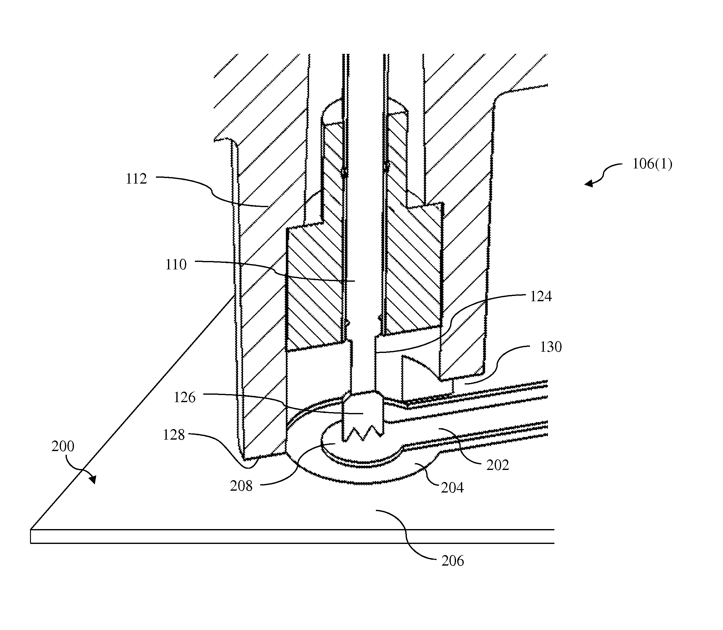
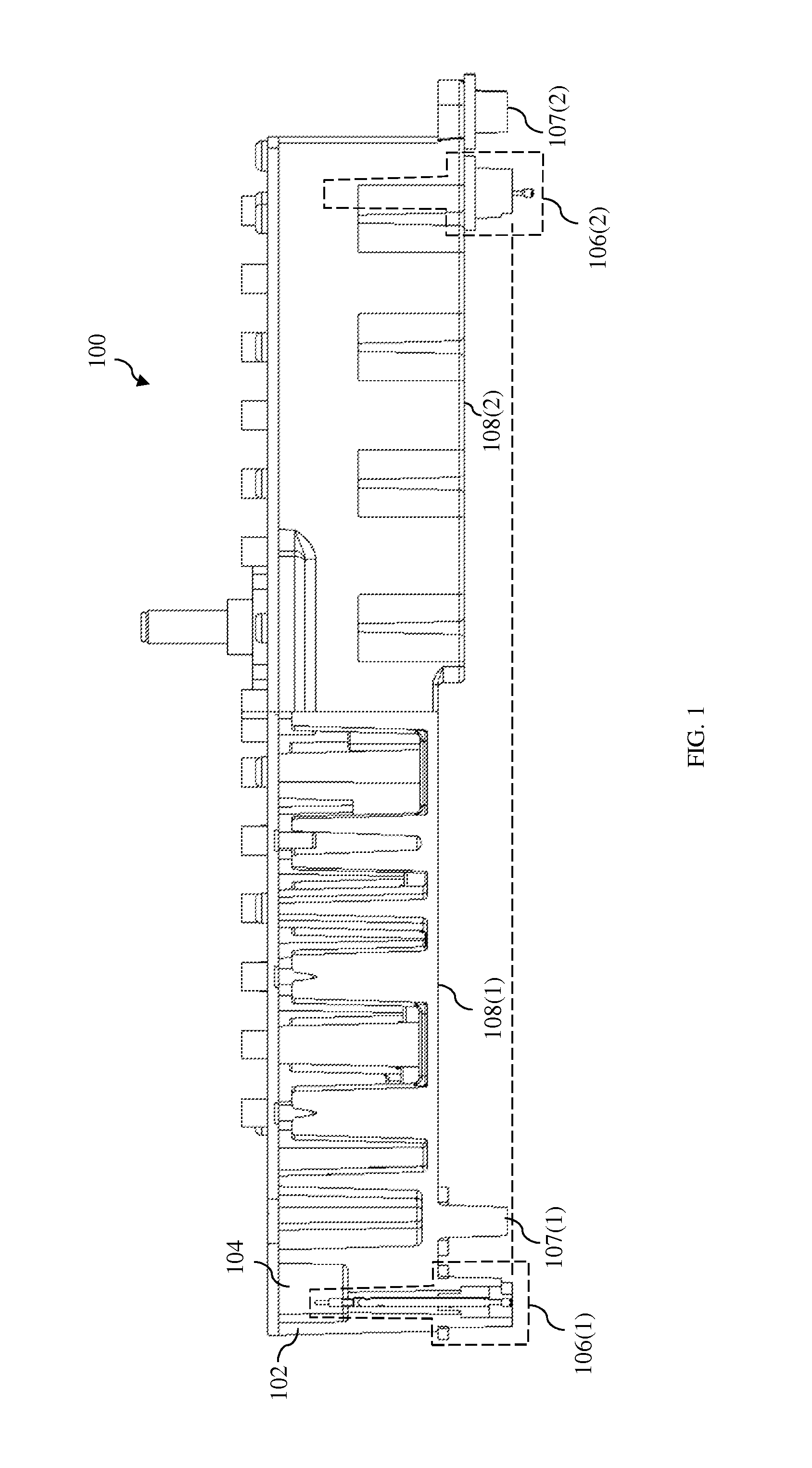
[0016]FIG. 1 shows a cross-sectional view of an electronic device 100 according to one embodiment of the disclosure. In this embodiment, electronic device 100 is an active antenna component. However, alternative embodiments of the disclosure may be implemented using any suitable electronic device that processes communications signals.

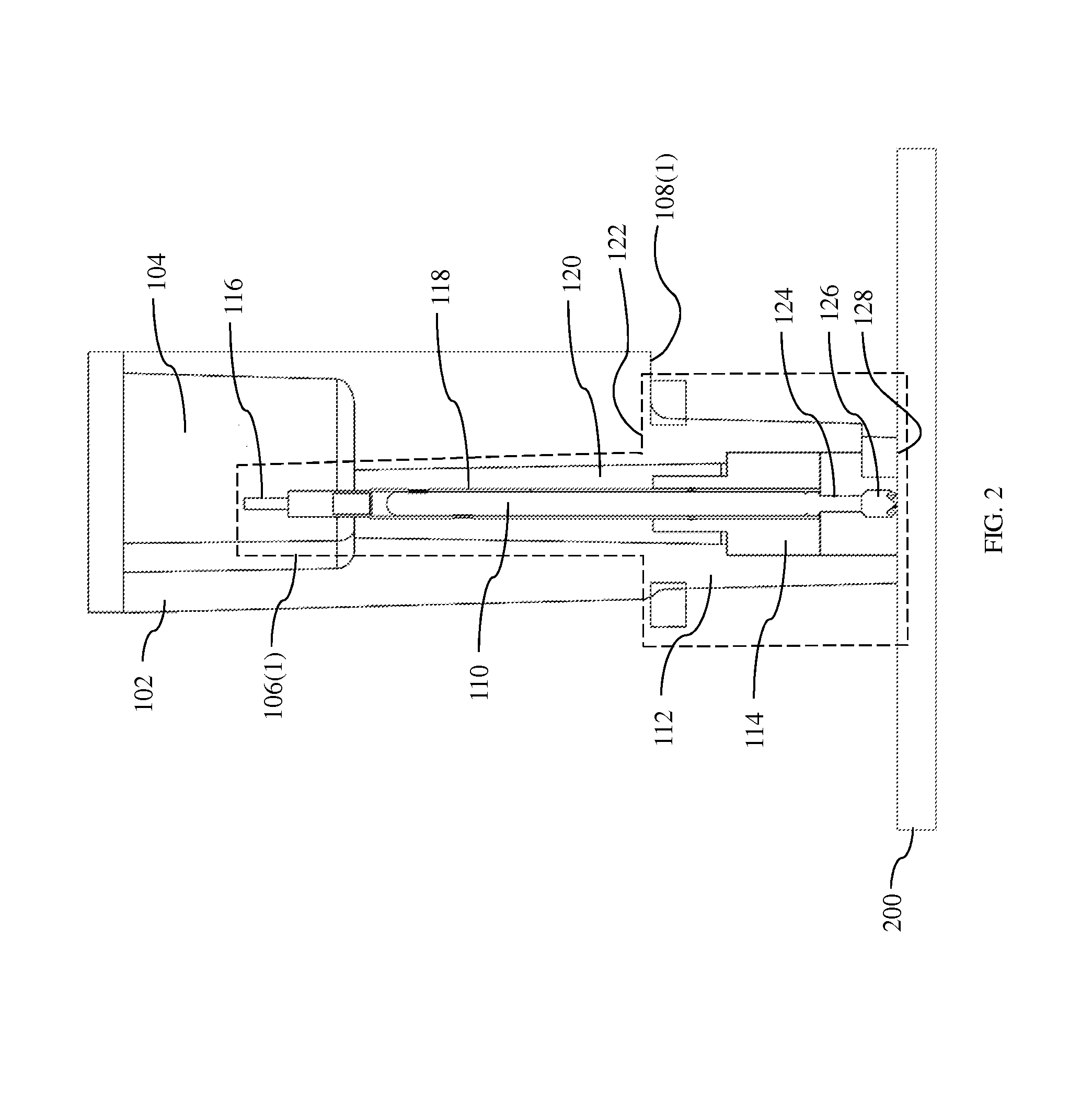
[0017]Electronic device 100 has (i) a housing 102 with one or more cavities 104 formed therein, (ii) circuitry (not shown) for processing RF ...


PUM


Abstract

An electronic device, configured to be blindly mated with a printed circuit board, comprises a housing and at least one RF interconnect. The RF interconnect comprises an outer conductor, an insulator, and an inner conductor that function in a manner similar to the outer conductor, insulator, and inner conductor of a coaxial cable, respectively. The inner conductor comprises a spring-loaded electrical contact such as a POGO pin. An upper end of the outer conductor is electrically coupled to the housing and a lower end of the outer conductor is configured to electrically couple to a ground return path of the printed circuit board. In its normally extended position, the spring-loaded contact extends beyond the lower end of the outer conductor, and the outer conductor limits the compression distance of the spring-loaded contact.

Description

CROSS-REFERENCE TO RELATED APPLICATIONS[0001]This application claims the benefit of the filing date of U.S. provisional application no. 61 / 656,577, filed on Jun. 7, 2012 as attorney docket no. 1052.103PROV, the teachings of all of which are incorporated herein by reference in their entirety.BACKGROUND[0002]1. Field of the Invention[0003]The present invention relates to electrical connections, and, more specifically but not exclusively, to connections for passing radio frequency (RF) signals and the like.[0004]2. Description of the Related Art[0005]An electronic device that uses radio frequency (RF) signals may need to pass RF signals to a printed circuit board. Conventionally, RF interconnects between electronic devices and printed circuit boards are made using an RF blind-mate connector pair or a combination of an RF connector and RF jumper cable. These conventional RF connector systems have several drawbacks. For instance, conventional connector systems are limited in the radial a...

Claims


Application Information

Patent Timeline
Patent Type & Authority Applications(United States)
IPC IPC(8): H01R12/71
CPCH01R12/714H01R13/2492H01R24/40
Inventor RUCKI, JOHN S.GELBSTEIN, JONATHAN H.COLAPIETRO, JULIAN R.
Owner COMMSCOPE TECH LLC
Why Eureka
Try Eureka