Centrifuge Drive Head For Releasably Connecting A Driving System To A Rotor Of A Centrifuge, A Set And A Centrifuge Comprising The Drive Head

Active Publication Date: 2013-12-12
QIAGEN
View PDF16 Cites 10 Cited by
  • Summary
  • Abstract
  • Description
  • Claims
  • Application Information

AI Technical Summary

Benefits of technology

[0025]As mentioned above, the coupling elements can be provided with a ramp shaped face. In this case, the notch pertaining to the respective coupling element also comprises a complementary ramp shaped stop face, against which the ramp shaped face of the outwardly pivoted coupling element can bear. Since the force exerted against the ramp shaped stop face when the coupling elements pivot into the notch rises with increasing pivotal movement, a certain degree of restriction of the pivotal path is also achieved in this way. Furthermore, the securing force acting between the coupling element and the hub can be set very precisely by varying the angle of inclination of the ramp shaped faces. Preferably, the ramp shaped stop faces are disposed in the region of the top or bottom wall that delimits the notch in the direction of the axis of rotation and that can be entirely, or only partially, in the form of a ramp shaped face.
[0026]Apart from the coupling elements and the associated notches, the drive head and the hub/rotor can be designed as is usual in the art. Preferably, both components rest positively against each other over large areas thereof, as far as possible, in order to ensure that the two components are supported against each other without play. The hub is guided very effectively and the drive head and the hub are secured against forming an angle of inclination when the base body of the drive head comprises a top region as regarded in the direction in which the rotor is fitted to the drive head, which top region has a substantially cylindrical external contour and ensures that the hub is centered and guided in the radial direction, and a bottom region in the form of a truncated cone that adjoins the top r

Problems solved by technology

However, the unlocking mechanism disclosed therein is difficultly available for many conventional designs of rotor, and the rotor is not guided sufficiently without play, which might result in dynamic instability at relatively high loads and rotational speeds.
However, it is only suitable for specific types of rotor that do not generate any

Method used


Image

  • Centrifuge Drive Head For Releasably Connecting A Driving System To A Rotor Of A Centrifuge, A Set And A Centrifuge Comprising The Drive Head
  • Centrifuge Drive Head For Releasably Connecting A Driving System To A Rotor Of A Centrifuge, A Set And A Centrifuge Comprising The Drive Head
  • Centrifuge Drive Head For Releasably Connecting A Driving System To A Rotor Of A Centrifuge, A Set And A Centrifuge Comprising The Drive Head

Examples


Example

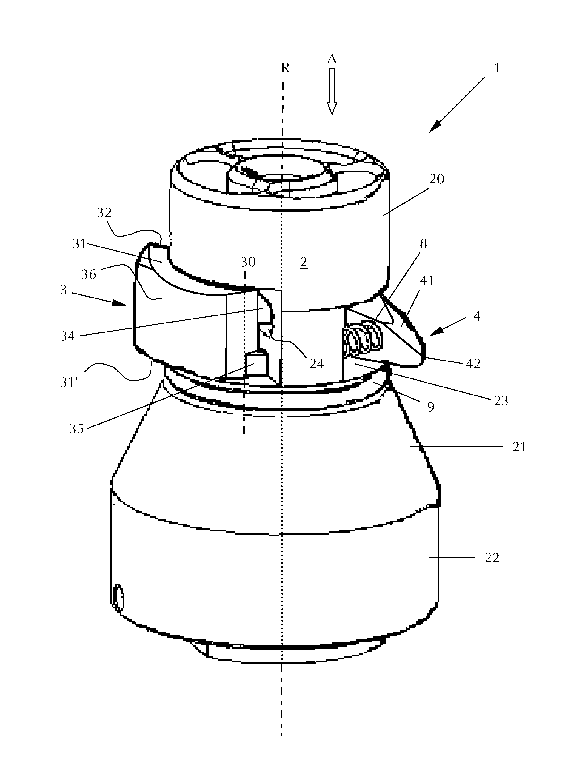
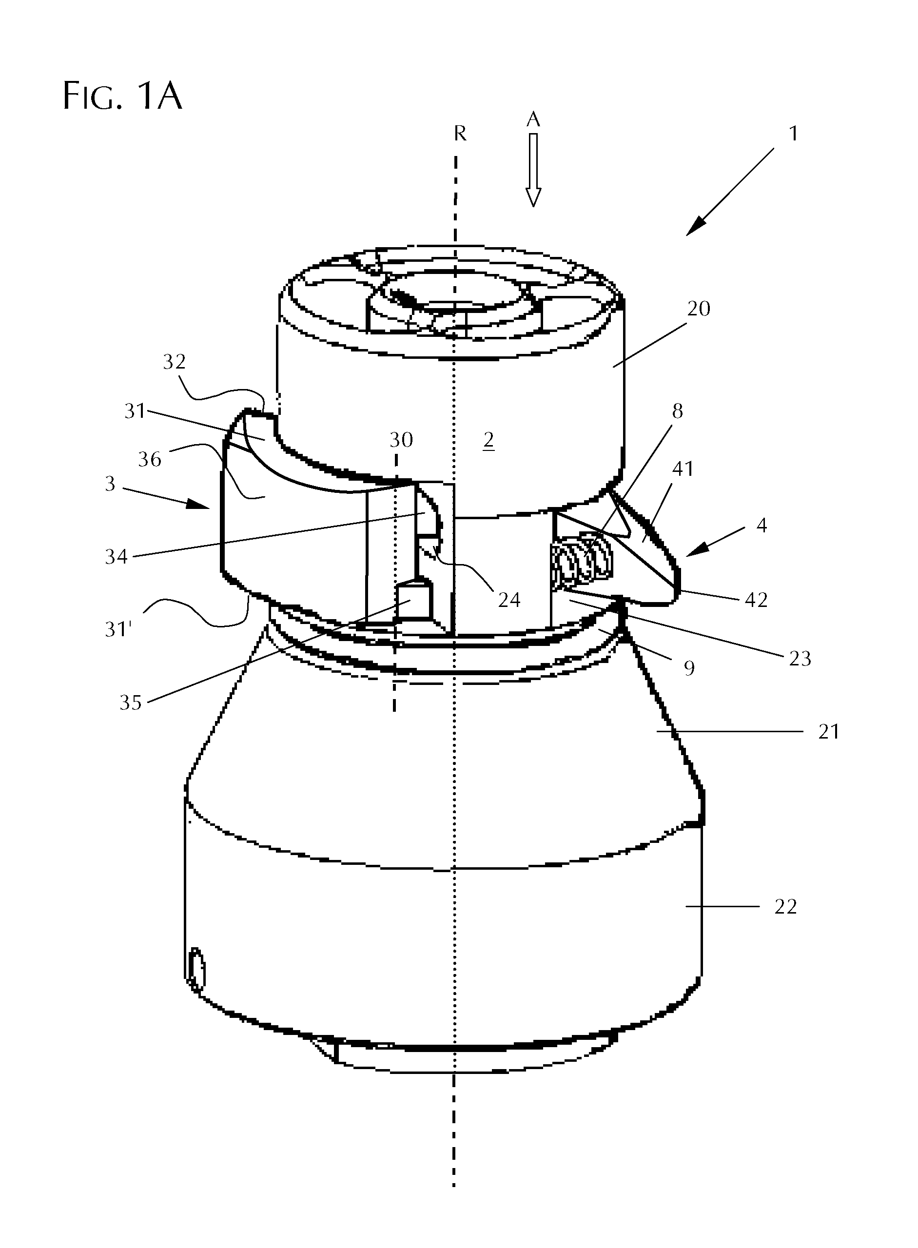
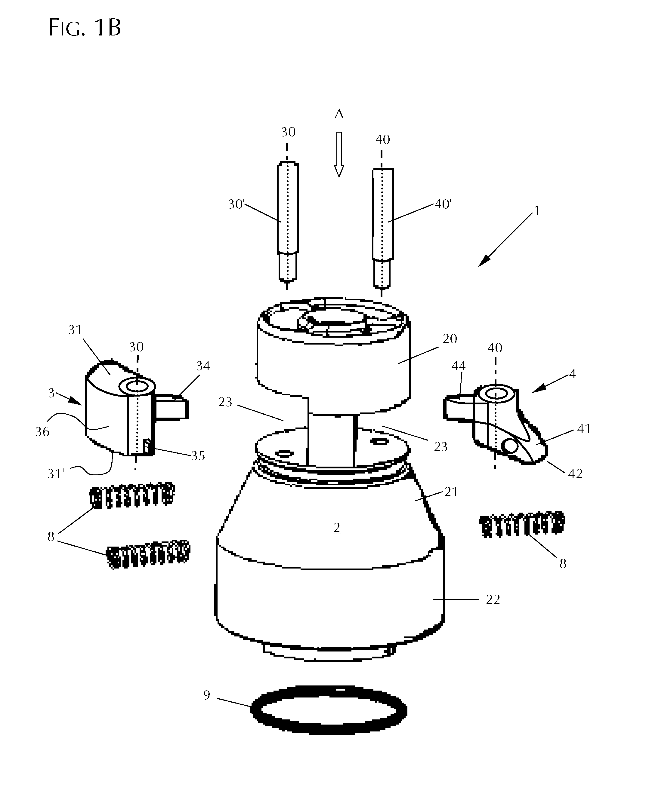
[0040]FIG. 1(A) is a perspective view of a centrifuge drive head 1 according to one embodiment of the present invention; FIG. 1(B) shows the same drive head in the form of an exploded view. The drive head 1 comprises a base body 2 comprising a substantially cylindrical top region 20 and a lower region 21 in the form of a truncated cone. This portion is adjoined by a bottom cylindrical region 22. Between the top region 20 and the lower region 21 of the drive head there are located two coupling elements 3 and 4 that are in the form of pivotal wedges.

[0041]According to one aspect of the present invention, the two coupling elements 3 and 4 differ from each other. In the example shown, they differ in terms of their geometric shape and material. The first coupling element 3 is larger and more massive than the second coupling element 4. The coupling element 3 is made of steel in the example shown while the coupling element 4 is made of titanium. Both steel and titanium have very high stren...


PUM


Abstract

The present invention relates a centrifuge drive head for releasably connecting a driving system to a rotor of a centrifuge. The centrifuge drive head comprises a base body mounted for rotation about an axis of rotation (R) and at least a first and a second coupling element, mounted on the base body for swinging outwardly about a swivel axis. The first and second coupling elements differ from each other.
The present invention further relates to a set for a centrifuge, which comprises, in addition to the centrifuge drive head, a hub of a rotor, into the recess of which the first and/or second coupling element can be swiveled depending on their configuration, and also to a centrifuge.

Description

CROSS-REFERENCE TO RELATED APPLICATIONS[0001]The present application claims priority under 35 U.S.C. §119 of German Patent Application No. 10 2012 011 531.8, filed Jun. 8, 2012, the disclosure of which is hereby incorporated herein by reference in its entirety.FIELD OF THE INVENTION[0002]The present invention relates to centrifuges that hold sample containers and are used for separating the constituents of the samples contained therein at a high rotational speed of a centrifuge rotor. More particularly, the present invention relates to a centrifuge drive head for releasably connecting a driving system to a rotor of a centrifuge, which drive head comprises a base body and at least two coupling elements capable of swinging outwardly from the same. The present invention further relates to a set for a centrifuge, which set consists of a centrifuge drive head and at least one hub for a rotor. Finally, the present invention also relates to a centrifuge comprising the drive head or the set...

Claims


Application Information

Patent Timeline
IPC IPC(8): B04B9/00
CPCB04B9/00B04B9/08F16D1/116B04B2009/085
Inventor BALLHAUSE, NORMANHENNE, SEBASTIAN
Owner QIAGEN
Why Eureka
Try Eureka