Dynamic Working Area

Active Publication Date: 2013-12-12
SANDVIK MINING & CONSTR OY
View PDF5 Cites 1 Cited by
  • Summary
  • Abstract
  • Description
  • Claims
  • Application Information

AI Technical Summary

Benefits of technology

[0018]An advantage of the method and arrangement of the invention is that the use of the actual current input parameters gives a considerably more accurate definition of a working area to be displayed to an operator than that achieved by u

Problems solved by technology
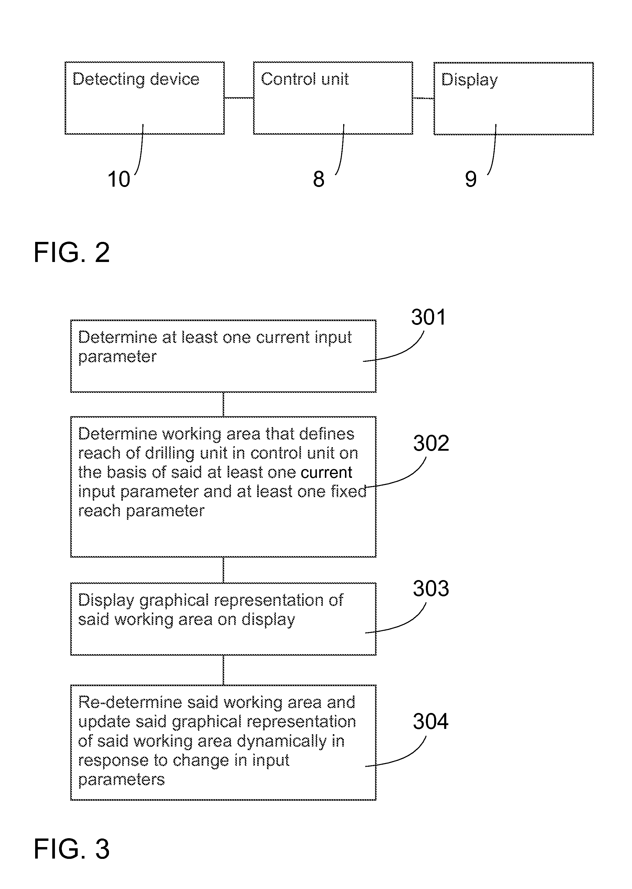
This kind of fixed working area is, however, always only an approximation and does not reflect the true wor

Method used


Image

  • Dynamic Working Area
  • Dynamic Working Area
  • Dynamic Working Area

Examples


Example

[0024]It will be obvious to a person skilled in the art that, as the technology advances, the inventive concept can be implemented in various ways. The present embodiments are not limited to the examples described above but may vary within the scope of the claims.

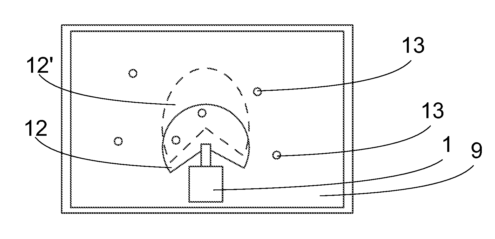
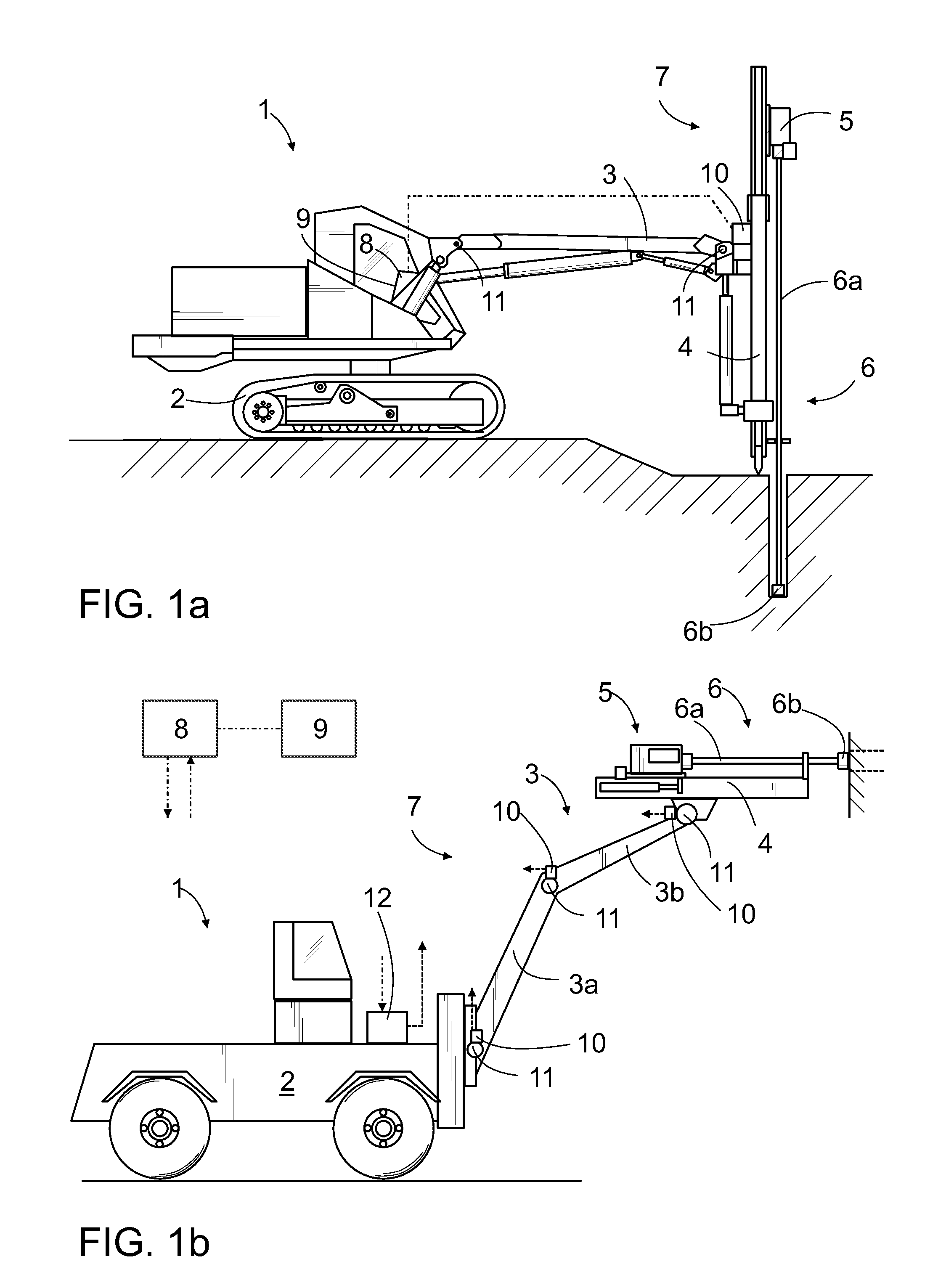
[0025]The rock drilling rig 1 shown in FIG. 1a comprises a mobile carrier 2 having one or more drilling booms 3 arranged thereto. A drilling unit 7 comprises a feed beam 4, a drilling machine 5 and a feed device arranged at one end of the boom 3. The drilling machine 5 is arranged movably on the feed beam 4 and can thus move along the feed beam 4 during operation. Drilling equipment 6 is arranged to the rock drilling machine 5. The drilling equipment 6 comprises one or more drill rods 6a and a tool 6b, e.g. a drilling bit, that are connected to each other in a manner known per se. A rock drilling rig 1 may also comprise one or several joints 11 joining, for example, the boom 3 to the movable carrier 2, the feed beam 4 to th...


PUM


Abstract

A method for defining a working area of a rock drilling rig including the steps of determining at least one current input parameter, determining a working area that defines a reach of the drilling unit in a control unit on the basis of the at least one current input parameter and at least one fixed reach parameter, displaying a graphical representation of the working area on a display, and re-determining the working area and updating the graphical representation of the working area dynamically in response to a change in the input parameters. The current input parameter may be, for example, an orientation of the rock drilling rig or a hole parameter.

Description

RELATED APPLICATION DATA [0001]The present application claims priority under 35 U.S.C. §119 to EP Patent Application No. 12171136 filed on Jun. 7, 2012, which the entirety thereof is incorporated herein by reference.SUMMARY [0002]The disclosed embodiments, that should be considered as non-limiting examples only, relate to a rock drilling rig, and more particularly to presenting a working area of a rock drilling rig on a display.[0003]At present, it is usual to use pre-determined hole parameters that may be based on drilling plans, for example. When tramming a drilling rig, the position of the drilling rig may be displayed in relation to one or more planned holes of a drilling plan on a display of a graphical user interface.[0004]User interfaces displaying some kind of working area of the rock drilling rig, i.e. an area presenting the drilling range of the rock drilling rig from its position, are also known. However, when presenting the drilling range in this way, the working area is...

Claims


Application Information

Patent Timeline
IPC IPC(8): G06F3/0484
CPCG06F3/0484E21D9/006E21B7/022E21B7/025
Inventor HEIKKILA, TOMMILASSILA, JUHASUVANEN, HENRI
Owner SANDVIK MINING & CONSTR OY
Why Eureka
Try Eureka