Method for detecting the extent of clear, intact track near a railway vehicle

a technology for railway vehicles and tracks, applied in the field of railway signaling, to achieve the effect of shortening the headway and improving the utilization efficiency of tracks

Inactive Publication Date: 2013-12-19
TRANSPORTATION TECH CENT
View PDF26 Cites 83 Cited by
  • Summary
  • Abstract
  • Description
  • Claims
  • Application Information

AI Technical Summary

Benefits of technology

[0011]Conventional fixed-block wayside signal systems use the track as a transmission line, transmitting and receiving pulsed codes indicating block or signal status. If equipped with a cab signal overlay system, codes are picked up by railway vehicles and used to convey signal status to the operator. The present invention receives track codes or cab signal codes on the vehicle using conventional pickup coils inductively coupled to the rails, and uses them as a positive indication of rail integrity. When codes are present on a track, they are detected, may be interpreted, and reception of the codes is communicated back, via an RF wireless link, to wayside equipment, office equipment, or equipment on a following train, which may be part of a CBTC or PTC system. Thus, an indication of rail integrity may be conveyed, directly or indirectly, to following trains, effectively extending signaling indications or movement authorities, or to relax a restriction, where appropriate. Indication of the presence of code behind a train, along with that train's location (e.g., from GPS) can be used by a CTC or PTC system to allow a following train to advance unrestricted to the leading train's end position.
[0012]Some embodiments of the present invention are fully compatible with existing traditional AC track circuit-based block signaling systems, particularly when implemented as an integral part of a CBTC or PTC system where train and traffic control functions are handled by radio communications rather than track circuits and wayside signals. Thus, in some embodiments, the present invention will allow existing traditional track-circuit based signaling infrastructure to be optimized for rail break detection rather than signaling. This could allow, for example, fewer and longer track circuits and / or improved rail break detection.
[0014]The present invention overcomes several fundamental limitations of conventional fixed-block track circuit broken rail detection, including the inherent minimum limit on train separation and track utilization efficiency. In railway terminology, this invention allows shorter headways.

Problems solved by technology

This is a function not performed by current fixed-block wayside signal systems, in that currently-used fixed-block wayside signal systems do not provide an indication that track immediately behind a train within the same block is unoccupied and free of rail breaks so that a following train could occupy it, unrestricted up to the leading train.

Method used


Image

  • Method for detecting the extent of clear, intact track near a railway vehicle
  • Method for detecting the extent of clear, intact track near a railway vehicle
  • Method for detecting the extent of clear, intact track near a railway vehicle

Examples


Embodiment Construction

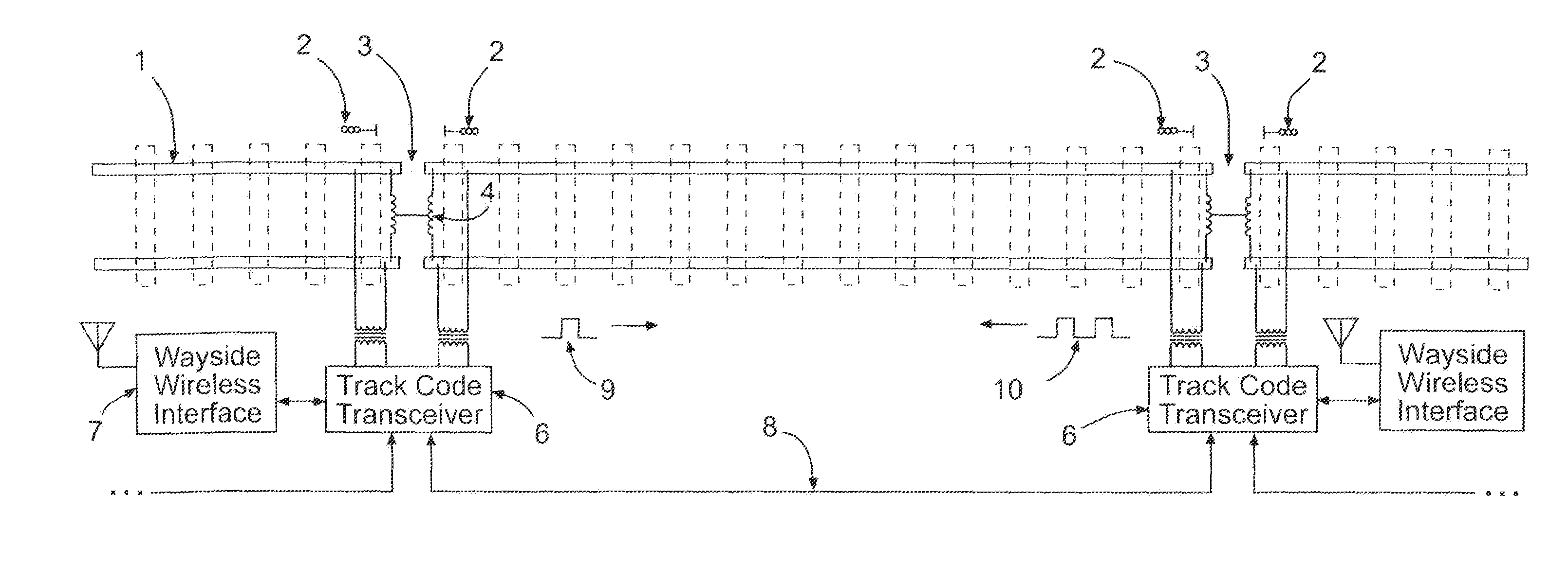
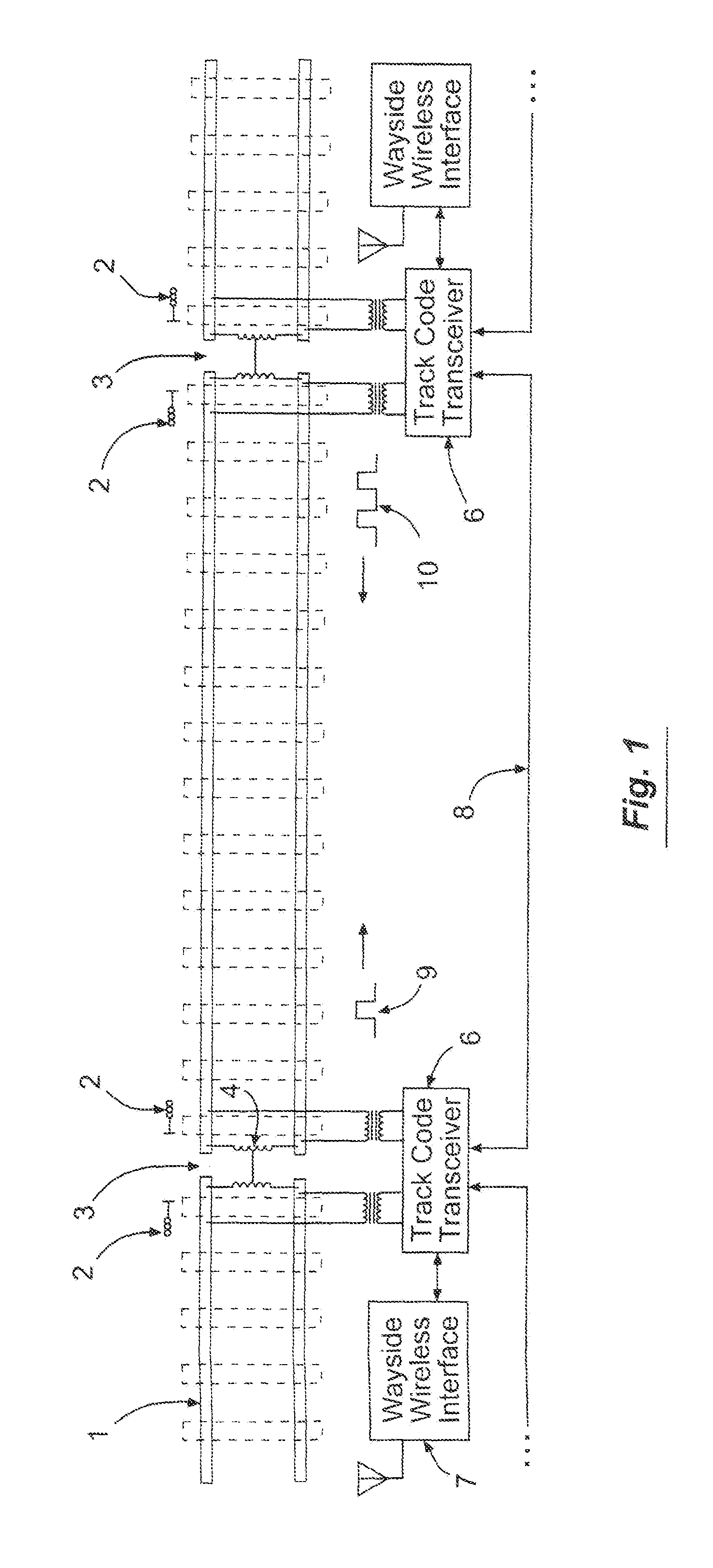
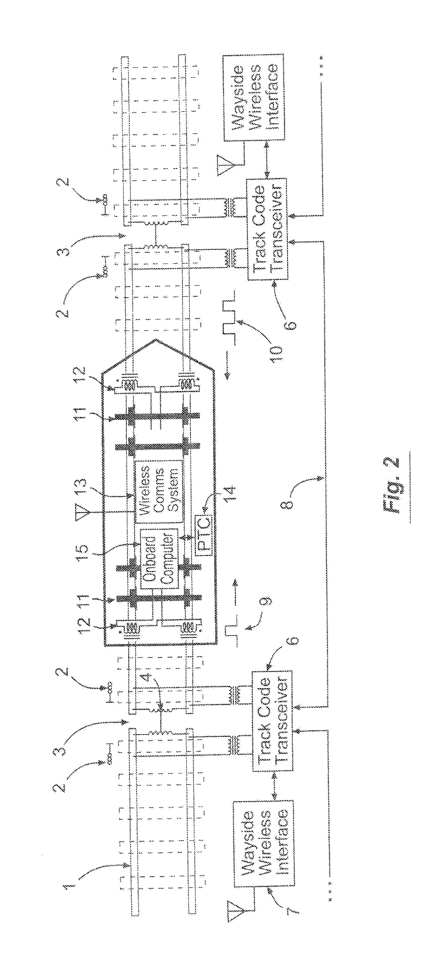
[0026]Before describing in detail the system and method for detecting broken rail or occupied track from a moving locomotive, it should be observed that the present invention resides primarily in what is effectively a novel combination of conventional electronic circuits, electronic components, and signal processing / estimation algorithms, and not in the particular detailed configurations thereof. Accordingly, the structure, control, and arrangement of these conventional circuits, components, and algorithms have been illustrated in the drawings by readily understandable block diagrams which show only those specific details that are pertinent to the present invention, so as not to obscure the disclosure with structural details which will be readily apparent to those skilled in the art having the benefit of the description herein. Thus, the block diagram illustrations of the figures do not necessarily represent the mechanical or structural arrangement of the exemplary system, but are p...


PUM


Abstract

A method is provided for detecting broken rail, track continuity, and track occupancy ahead of or behind a railroad vehicle traveling in fixed-block territory equipped with an AC track code wayside signal system or cab signal overlay system, and a communications link. This method, when used as an integral part of a communications-based train control (CBTC) or positive train control (PTC) system, allows immediate, automatic detection of broken rail, track occupancies, or open turnouts ahead of or behind a train in an occupied block. It also facilitates true moving-block or virtual block CBTC or PTC, thereby enabling higher efficiency and track utilization.

Description

RELATED APPLICATION[0001]The present application is based on and claims priority to the Applicants' U.S. Provisional Patent Application 61 / 660,076, entitled “Method For Detecting The Extent Of Clear, Intact Track Near A Railway Vehicle,” filed on Jun. 15, 2012.BACKGROUND OF THE INVENTION[0002]Field of the Invention. The present invention relates generally to railway signaling and more particularly, to rail break or vehicle occupancy detection on railroad track. More specifically, the present invention is in the technical field of railroad signaling and train control, including positive train control (PTC), centralized traffic control (CTC), automatic block signaling (ABS), communications-based train control (CBTC) and cab signaling.[0003]Background of the Invention. Conventional railway wayside signaling systems employ the rails of the track for transmission of signals used to detect track occupancy, broken rail and / or open turnouts. Railroad track is physically divided into a plura...

Claims


Application Information

Patent Timeline
Patent Type & Authority Applications(United States)
IPC IPC(8): B61L23/04B61L27/00
CPCB61L23/044B61L27/00B61L1/187B61L3/243B61L15/0027B61L21/10B61L23/166B61L2027/204B61L27/20
Inventor MALONE, JR., JEROME J.POLIVKA, ALAN L.
Owner TRANSPORTATION TECH CENT
Why Eureka
Try Eureka