
Alignment film, method of manufacturing the alignment film, retardation film, method of manufacturing the retardation film, and display

a technology of alignment film and retardation film, which is applied in the field of alignment film, can solve the problems of affecting the display effect, and requiring enormous effort and/or cost, so as to prevent the occurrence of a large amount of static electricity, prevent the occurrence of static charge, and prevent the occurrence of static electricity

Inactive Publication Date: 2013-12-19
SATURN LICENSING LLC
View PDF5 Cites 8 Cited by
  • Summary
  • Abstract
  • Description
  • Claims
  • Application Information

AI Technical Summary

Benefits of technology

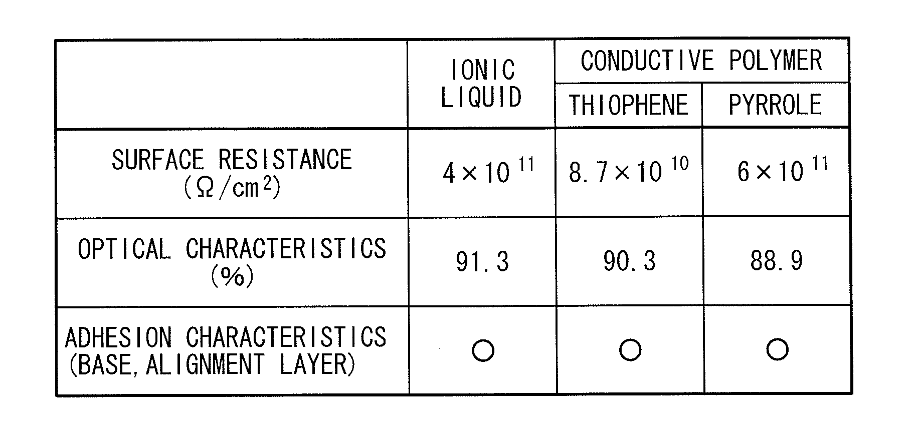
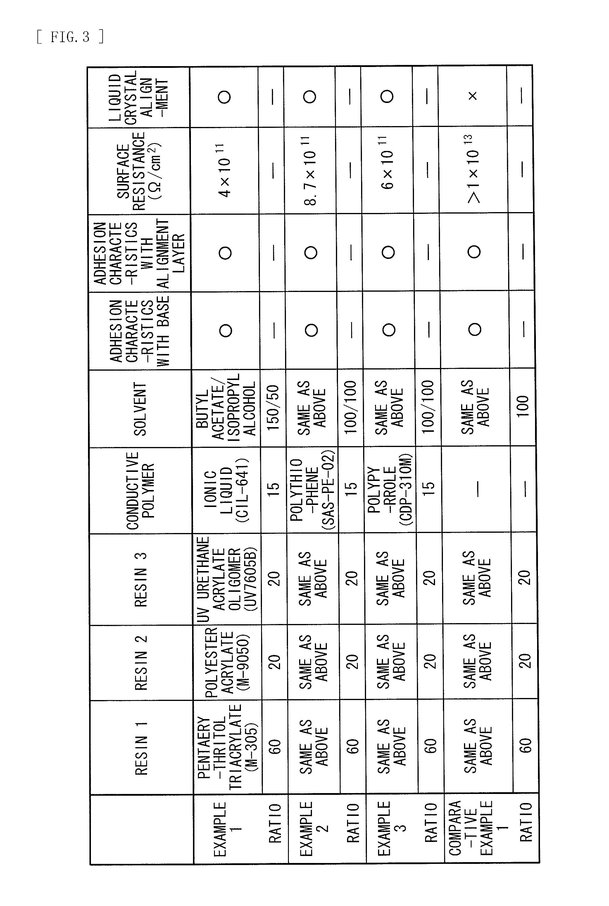
The invention provides an alignment film, retardation film, and display that can prevent alignment disorder caused by static electricity during the manufacturing process. The invention achieves this by reducing static electricity generated on the film using an anchor layer or protective layer with high surface resistance. This helps to avoid the need for special equipment or layers to prevent static charge. The invention thus simplifies the manufacturing process and reduces the likelihood of alignment disorder.

Problems solved by technology

As a result, for example, a large amount of static electricity is generated on, for example, an alignment film during a manufacturing process, and thus, alignment disorder occurs in the alignable material on the alignment film, which may disadvantageously cause streaks and / or unevenness in a displayed image.
Such an approach, however, disadvantageously takes enormous effort and / or cost.

Method used


Image

  • Alignment film, method of manufacturing the alignment film, retardation film, method of manufacturing the retardation film, and display
  • Alignment film, method of manufacturing the alignment film, retardation film, method of manufacturing the retardation film, and display
  • Alignment film, method of manufacturing the alignment film, retardation film, method of manufacturing the retardation film, and display

Examples


first embodiment

1. First Embodiment

[Configuration]

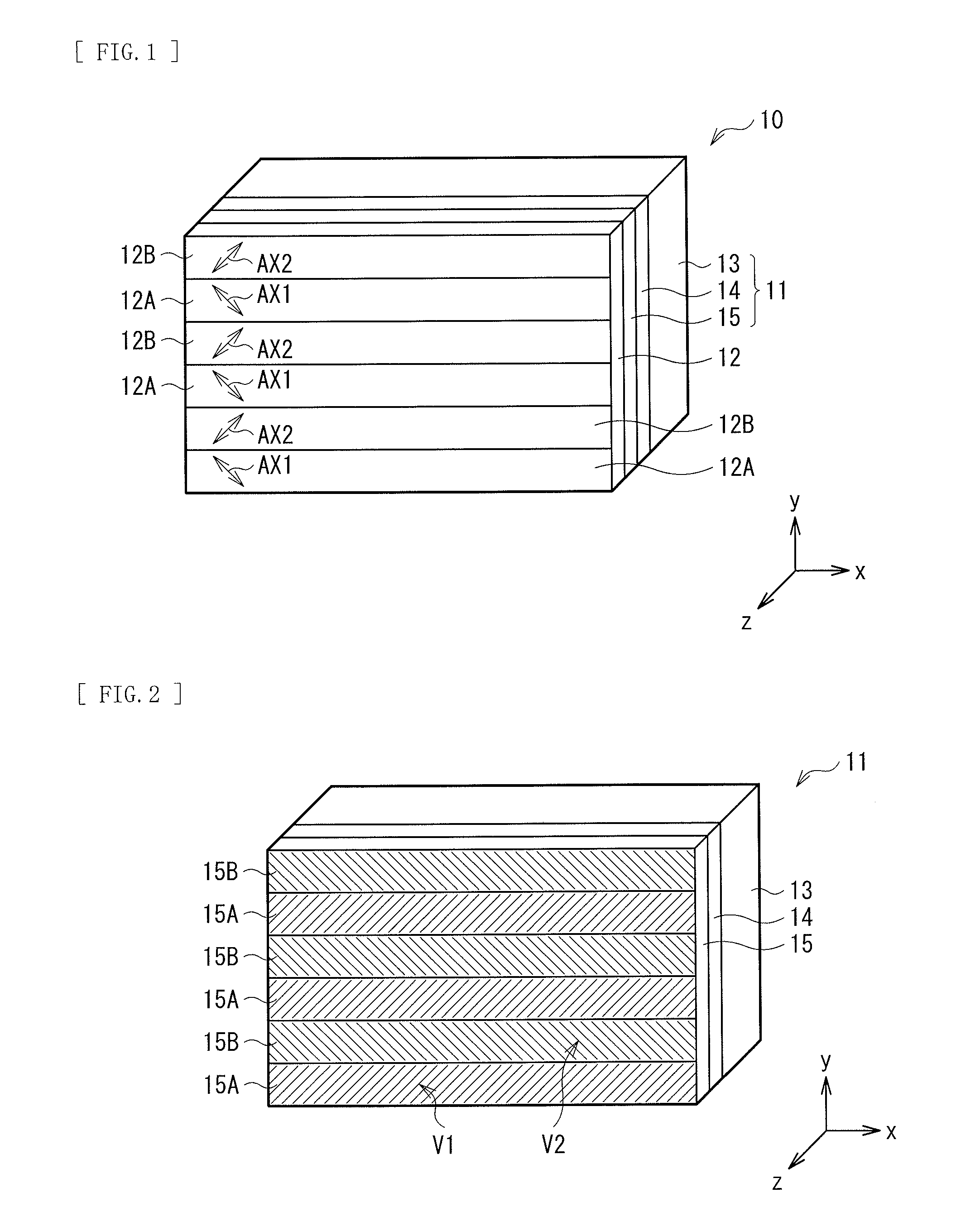
[0054]FIG. 1 perspectively illustrates an exemplary configuration of a retardation film 10 according to a first embodiment of the present invention. For example, as illustrated in FIG. 1, the retardation film 10 of the present embodiment has a retardation layer 12 on an alignment film 11. The alignment film 11 is, for example, formed of an anchor layer 14 and an alignment layer 15 stacked on a base 13 in this order of closeness to the base 13.

[0055]The base 13 secures stiffness of the retardation film 10 as a whole, and is formed of a transparent resin film, for example. The base 13 is preferably formed of a material having a small optical anisotropy, namely, a material having a small birefringence. Examples of the transparent resin film having such characteristics include TAC (triacetylcellulose), COP (cycloolefin polymer), COC (cycloolefin copolymer), and PMMA (polymethylmethacrylate). Examples of COP include ZEONOR and ZEONEX (registered trademar...

second embodiment

2. Second Embodiment

[Configuration]

[0096]FIG. 12 perspectively illustrates an exemplary configuration of a retardation film 20 according to a second embodiment of the present invention. For example, as illustrated in FIG. 12, the retardation film 20 of the present embodiment includes a protective layer 16 on the back of the base 13, and the alignment layer 15 and the retardation layer 12 in this order of closeness to the base 13 on the front surface (main surface) of the base 13. It is to be noted that the retardation film 20 may have an anchor layer, which brings the alignment layer 15 into close contact with the base 13, between the base 13 and the alignment layer 15. It is to be noted that the anchor layer may correspond to the anchor layer 14 in the above-described first embodiment, or may be a layer having only the function of bringing the alignment layer 15 into close contact with the base 13.

[0097]The protective layer 16 is, for example, laminated on the back of the base 13 s...

application example

3. Application Example

[0100]FIG. 13 illustrates an exemplary configuration of a display 1 according to an application example of the retardation film 10 (or the retardation film 20) of the above-described embodiment. The display 1 is a polarizing-glasses type of display that displays a stereoscopic image to an observer (not illustrated) wearing polarizing glasses 2 described later in front of his / her eye balls. The display 1 is formed of a backlight unit 3, a display panel 4, and the retardation film 10 (or the retardation film 20) stacked in this order. In the display 1, the retardation film 10 (or the retardation film 20) is bonded to the surface on a light emission side of the display panel 4. The surface of the retardation film 10 (or the retardation film 20) is an image display surface, and is directed to the observer.

[0101]It is to be noted that, in the present application example, the display 1 is disposed such that the image display surface is parallel to a perpendicular sur...


PUM


Abstract

An alignment film capable of reducing occurrence of alignment disorder in a simple manner, a method of manufacturing the alignment film, a retardation film, a method of manufacturing the retardation film, and a display are provided. An alignment film is configured of an anchor layer and an alignment layer stacked in this order on a base. The alignment layer includes a groove region having a plurality of fine grooves on a surface thereof, and a groove region having a plurality of fine grooves on a surface thereof. The anchor layer provided between the base and the alignment layer is provided with an antistatic function in addition to a function of bringing the alignment layer into close contact with the base.

Description

TECHNICAL FIELD [0001]The present invention relates to an alignment film having fine grooves of nanometer order scale on a surface thereof, and to a method of manufacturing the alignment film. Also, the present invention relates to a retardation film including a retardation layer on the surface of the above-described alignment film, and to a method of manufacturing the retardation film. Furthermore, the present invention relates to a display including the above-described retardation film.BACKGROUND ART [0002]In the past, there has been a stereoscopic image display of a type using polarizing glasses, that includes left-eye pixels and right-eye pixels emitting light in different polarization states. In such a display, while an observer wears polarizing glasses, light emitted from each left-eye pixel is incident only on the left eye, and light emitted from each right-eye pixel is incident only on the right eye, so that observation of a stereoscopic image is achieved.[0003]For example, ...

Claims


Application Information

Patent Timeline
Patent Type & Authority Applications(United States)
IPC IPC(8): G02B5/30B05D3/12
CPCG02B5/30B05D3/12G02B5/3083G02B27/0006G02F1/13363Y10T428/2457C09K2323/02G02B30/00B32B2457/202G02B1/14G02B1/16G02B1/18
Inventor KURIYAMA, AKITOOHYANAGI, EIKIINOUE, JUNICHIOBATA, KEI
Owner SATURN LICENSING LLC
Learn More