Systems and methods for dynamic routing in a cluster

a cluster and dynamic routing technology, applied in data switching networks, high-level techniques, digital transmission, etc., can solve the problems of interface muting, excessive bandwidth consumption, etc., and achieve the effect of preventing loops and muting, and distributing packets efficiently and efficiently among connections

Active Publication Date: 2013-12-19
CITRIX SYST INC
View PDF3 Cites 46 Cited by
  • Summary
  • Abstract
  • Description
  • Claims
  • Application Information

AI Technical Summary

Benefits of technology

[0004]The present application is directed towards systems and methods for distributing multicast routing packets in a cluster environment utilizing link aggregation. In many embodiments of cluster environments, a plurality of devices may be connected to an upstream router or switch and present themselves as a single “virtual” device having a plurality of connections to the device as part of a link aggregation group, allowing the router to easily and efficiently distribute packets among the connections. Multicast routing packets may be sent via only a single connection of the link aggregation group, and accordingly, a recipient device of the plurality of devices may distribute the multicast routing packet via a back plane to other devices. In some embodiments, to distinguish between a newly received routing packet from the router, and an internally distributed routing packet from a first device of the cluster, the first device may insert a predetermined identifier into a MAC address of the routing packet. Other devices may determine, based on the presence of the identifier, that the packet has been forwarded and may accordingly not re-forward the packet, preventing loops and muting.

Problems solved by technology

The recipient node may re-distribute the packet via the back plane, but if other nodes cannot distinguish between a re-distributed packet and the original multicast routing packet, they may themselves re-distribute the packet via the back plane, resulting in looping, excess bandwidth consumption, and interface muting.

Method used


Image

  • Systems and methods for dynamic routing in a cluster
  • Systems and methods for dynamic routing in a cluster
  • Systems and methods for dynamic routing in a cluster

Examples


Embodiment Construction

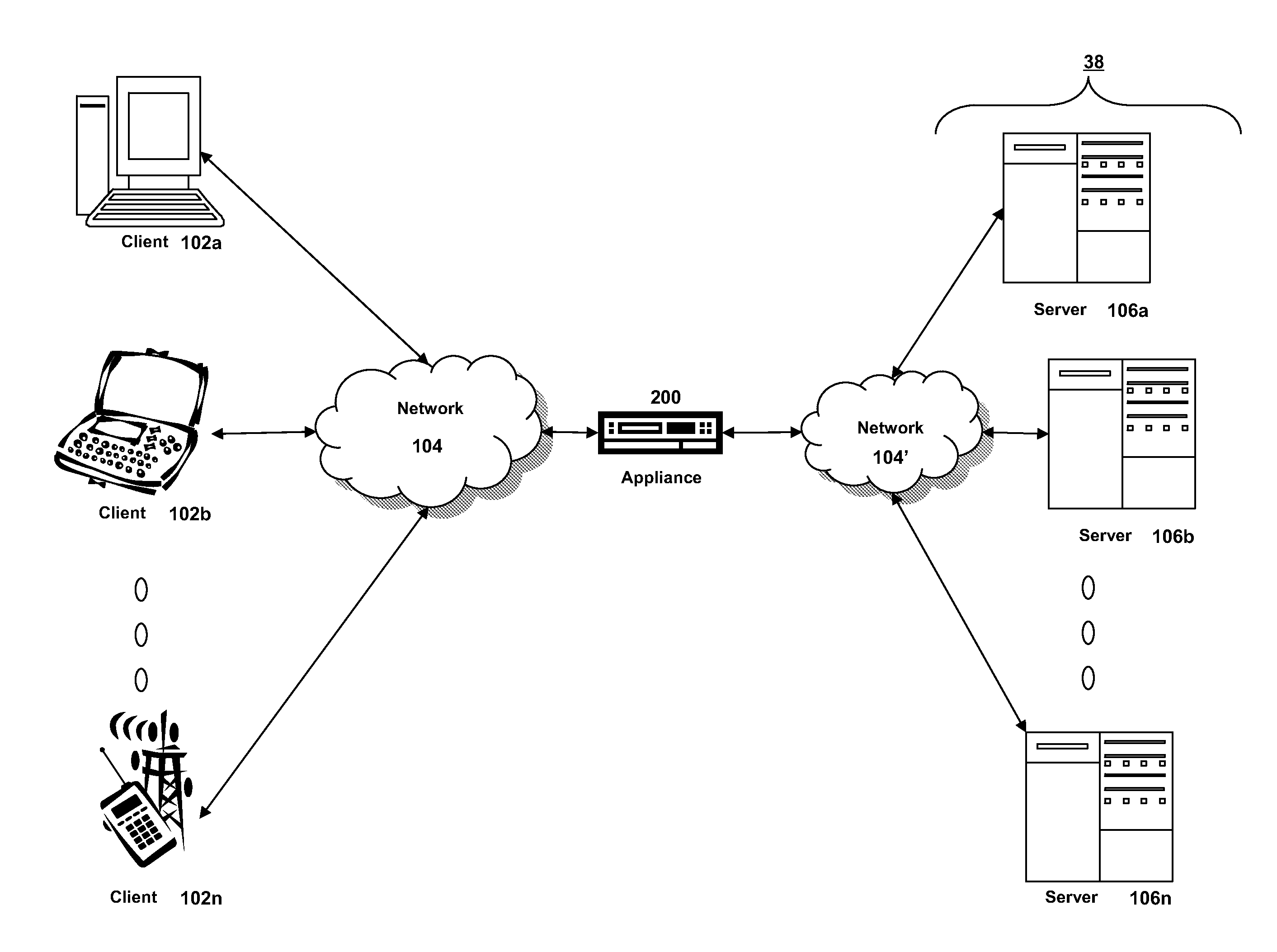
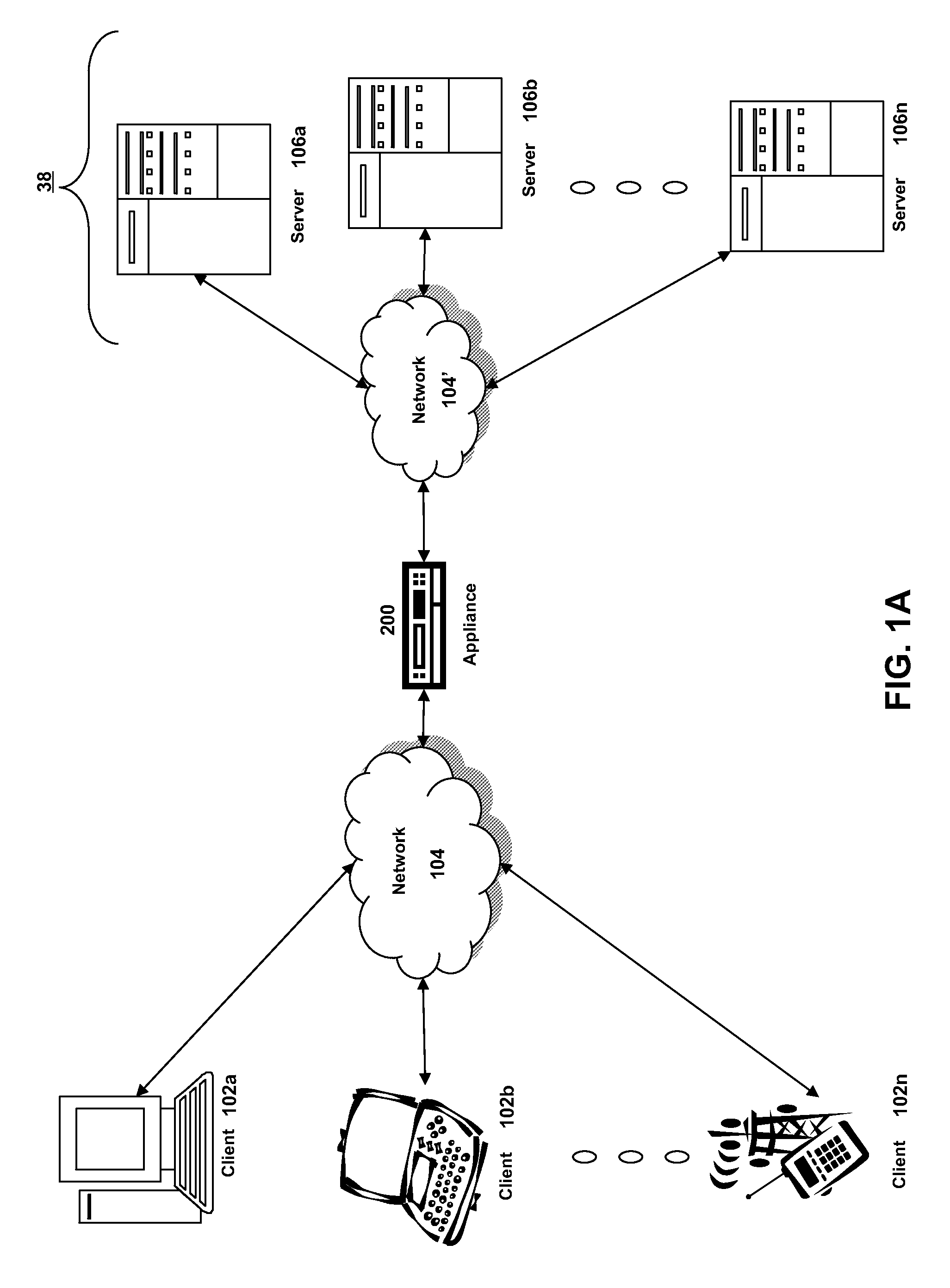
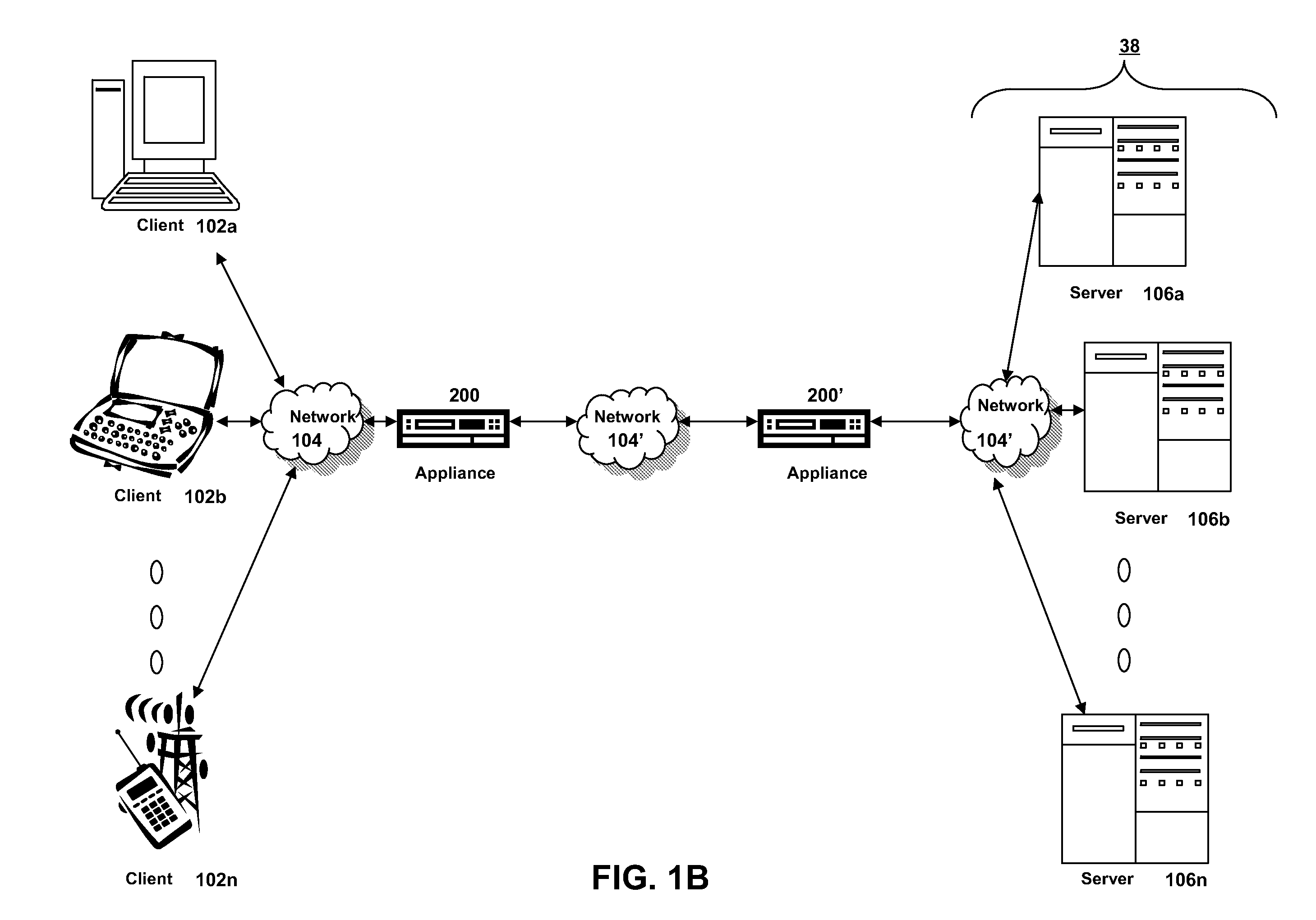
[0035]For purposes of reading the description of the various embodiments below, the following descriptions of the sections of the specification and their respective contents may be helpful:[0036]Section A describes a network environment and computing environment which may be useful for practicing embodiments described herein;[0037]Section B describes embodiments of systems and methods for delivering a computing environment to a remote user;[0038]Section C describes embodiments of systems and methods for accelerating communications between a client and a server;[0039]Section D describes embodiments of systems and methods for virtualizing an application delivery controller;[0040]Section E describes embodiments of systems and methods for providing a multi-core architecture and environment;[0041]Section F describes embodiments of systems and methods for providing a clustered appliance architecture environment;[0042]Section G describes embodiments of systems and methods for dynamic routi...


PUM


Abstract

The present application is directed towards distributing multicast routing packets in a cluster environment utilizing link aggregation. In a cluster environment, a plurality of devices may be connected to an upstream router or switch as a single “virtual” device having a plurality of connections as part of a link aggregation group, allowing the router to easily and efficiently distribute packets among the connections. Multicast routing packets may be sent via only a single connection of the link aggregation group, and accordingly, a recipient device may distribute the multicast routing packet to other devices. To distinguish between a newly received routing packet from the router and an internally distributed routing packet from a first device, the first device may insert a predetermined identifier into a MAC address of the routing packet.

Description

FIELD OF THE INVENTION[0001]The present application generally relates to data communication networks. In particular, the present application relates to systems and methods for distributing multicast routing packets in a cluster environment utilizing link aggregation.BACKGROUND OF THE INVENTION[0002]In some cluster systems, a plurality of nodes of the cluster may be connected to upstream routers or switches. In some embodiments, through the use of link aggregation, the nodes may appear to the upstream router to be a single device with multiple connections. The router may send packets down different connections to the individual devices of the cluster, which may then steer or distribute the packets to processing nodes as necessary, such as via a common data back plane.[0003]Some packets may need to be sent to all devices of the cluster or all nodes connected to the router, such as multicast routing packets. However, in many embodiments, due to the link aggregation making it appear to ...

Claims


Application Information

Patent Timeline
Patent Type & Authority Applications(United States)
IPC IPC(8): H04L12/56H04L45/16H04L45/18H04L45/243H04L45/586
CPCH04L45/16H04L45/18H04L45/245H04L45/586Y02D30/50H04L61/5038H04L61/4511H04L2101/622
Inventor MITHYANTHA, SHARVARIBIRUDURAJU, SUREKHA
Owner CITRIX SYST INC
Why Eureka
Try Eureka