Carrier for Pipette Tips

Active Publication Date: 2013-12-19
EPPENDORF SE
View PDF3 Cites 23 Cited by
  • Summary
  • Abstract
  • Description
  • Claims
  • Application Information

AI Technical Summary

Benefits of technology

[0063]According to a further embodiment, the upper plates have, on an apron-like, downwardly protruding edge area, inwardly protruding locking tabs and the locking elements of the distance piece are locked with the locking tabs of the upper plate. The locking is easily established by bending the apron-like, downwardly protruding edge of the upper plates ou

Problems solved by technology

The known refill package is not well suited for the utilisation in automatic machines.
Displacement of the cover cap by an automatic machine in order to separate plate and cover cap would be problematic due to the cover cap's flexibility.
However, detaching the plate from the lower part is only possible by the expenditure of a force that is greater than the weight force of lower part and plate.
Automatic refilling of pipette tips into the box would be a problem.
In particular, replacing a plate by a plate equipped with new syringes would be hard to perform for an automatic machine.
This could not be managed by conventional automatic machines.
Thus, it is a disadvantage of such a box that the pipette tips hit the grid-like subdivision when being inserted, and fall out of the plate.
This arrangement requires much space and material.
This system saves space and material.
However, it is only suitable for nestable pipette tips.
The system is not suitable for non-nestable pipette tips, in particular for pipette tips with a cylindrical section and for filter pipette tips, because they are only partially nestable and hereby wedge together

Method used


Image

  • Carrier for Pipette Tips
  • Carrier for Pipette Tips
  • Carrier for Pipette Tips

Examples


embodiment 1

[0155]An alternative embodiment identified as embodiment 1 includes: A carrier for pipette tips, with

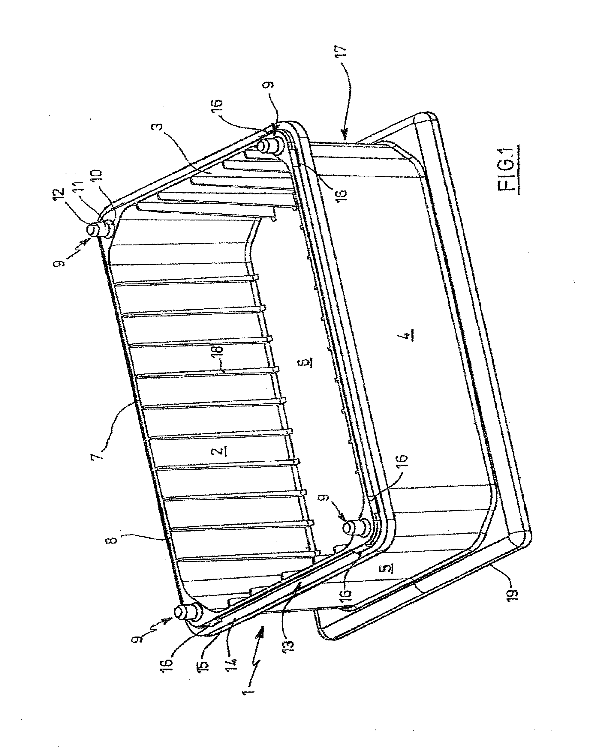
[0156]a frame (1), featuring four side walls (2 to 5),

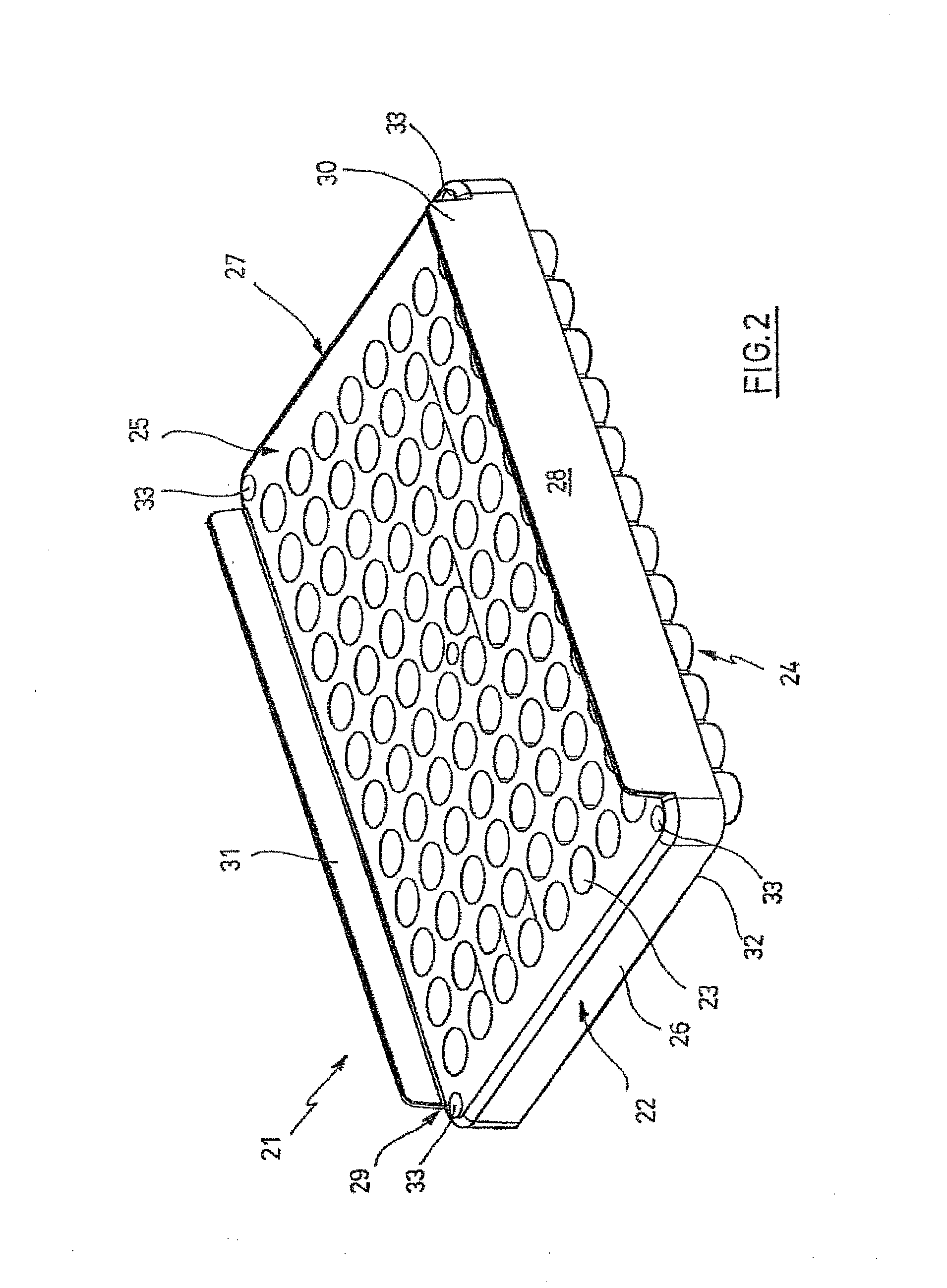
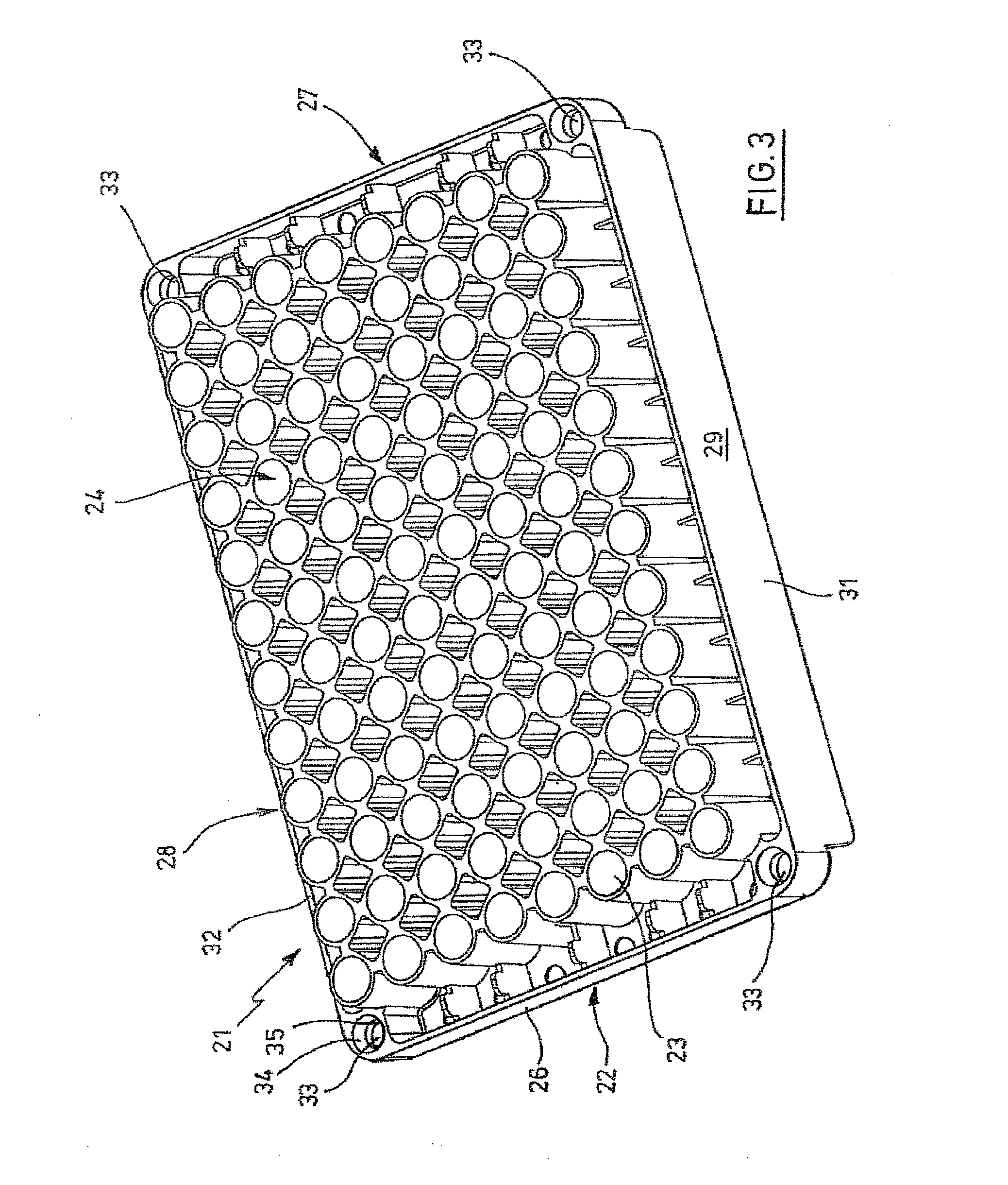
[0157]a plate (21) with a plurality of holes (23) for inserting pipette tips (36) and

[0158]means for detachably connecting the frame (1) and the plate (21),

[0159]that have contact surfaces (8, 32) on the upper edge (7) of the frame (1) and on the underside (24) of the plate (21), which touch each other when the plate is put onto the frame (1), and

[0160]that have guiding elements (9, 33) directed transversally to the contact surfaces on the frame (1) and on the plate (21), which engage into each other with lateral clearance when the plate (21) is put onto the frame (1).

[0161]An alternative embodiment identified as embodiment 2 includes: A carrier for pipette tips according to alternative embodiment 1, wherein the guiding elements (9, 33) are arranged at opposing side walls (2 to 5) of the frame (1) and at opposing edges of the plat...

embodiment 3

[0162]An alternative embodiment identified as embodiment 3 includes: A carrier according to alternative embodiments 1 or 2, wherein the guiding elements are adapted to be brought into engagement with each other with lateral clearance feature columns (9), and bores (33) suited for insertion of the columns with lateral clearance, and / or ribs and grooves that are suited for insertion of the ribs with lateral clearance.

[0163]An alternative embodiment identified as embodiment 4 includes: A carrier according to alternative embodiment 3, wherein the columns (9) and / or the ribs project from the upper edge (7) of the frame (1) and the plate feature the bores (33) and / or grooves in the underside (24).

embodiment 5

[0164]An alternative embodiment identified as embodiment 5 includes: A carrier according to any one of alternative embodiments 1 to 4, wherein the columns (9) and / or ribs taper at least in sections in the direction towards their free end, and / or wherein the bores (33) and / or grooves widen up at least in sections in the direction towards their insertion openings for the columns (9) and / or ribs.


PUM


Abstract

A carrier for pipette tips, with
    • a frame, featuring four side walls,
    • a plate with a plurality of holes for inserting pipette tips, and
    • means for detachably connecting the frame and the plate,
    • that have contact surfaces on the upper edge of the frame and on the underside of the plate, which touch each other when the plate is put onto the frame, and
    • that have guiding elements directed transversally to the contact surfaces on the frame and on the plate, which engage into each other with lateral clearance when the plate is put onto the frame.

Description

CROSS-REFERENCE TO RELATED APPLICATIONS[0001]This application is a Continuation-in-Part of U.S. patent application Ser. No. 12 / 691,198, filed on Jan. 20, 2010, which claims the benefit of U.S. Provisional Patent Application Ser. No. 61 / 146,818, filed on Jan. 23, 2009, which is incorporated herein by reference in its entirety.BACKGROUND OF THE INVENTION[0002]The present invention is related to a carrier for pipette tips, for those in automatic machines in particular. Furthermore, the invention relates to a distance piece for holding an upper plate with a plurality of holes for inserting pipette tips spaced from a lower plate with a plurality of holes for holding pipette tips.[0003]Carriers for pipette tips serve for keeping and providing pipette tips made of plastic material for utilisation. They have an edge with four upwardly projecting side walls and a plate, disposed on the upper edge of the frame and having a plurality of holes in a matrix arrangement. Pipette tips are put into ...

Claims


Application Information

Patent Timeline
IPC IPC(8): B01L9/00
CPCB01L9/543B01L2200/025B01L2200/028
Inventor RETHWISCH, HANNABLUMENTRITT, MICHAEL
Owner EPPENDORF SE
Why Eureka
Try Eureka