Firing mechanism for a firearm

a firing mechanism and firearm technology, applied in the field of firearms, can solve the problems of affecting accuracy, useless, and affecting the firing mechanism of the firearm, and achieve the effect of reducing the number of firing mechanisms

Active Publication Date: 2013-12-26
APEX TACTICAL SPECIALTIES
View PDF10 Cites 19 Cited by
  • Summary
  • Abstract
  • Description
  • Claims
  • Application Information

AI Technical Summary

Benefits of technology

[0010]In another embodiment, a sear for a firearm comprises a longitudinal member, a fulcrum opening in the longitudinal member substantially perpendicular to the longitudinal axis of the longitudinal member, and a camming portion disposed on the forward portion of the sear and comprising a camming surface for engagement by a trigger assembly. The fulcrum opening can be configured to receive a fulcrum body and to allow the longitudinal member to rotate about the fulcrum body, the fulcrum opening effectively partitioning the longitudinal member into a forward portion and a rearward portion. Additionally, a distance from the center of the fulcrum body to a point of engagement of the trigger assembly on the camming surface can be at a minimum approximately 0.2 inches.
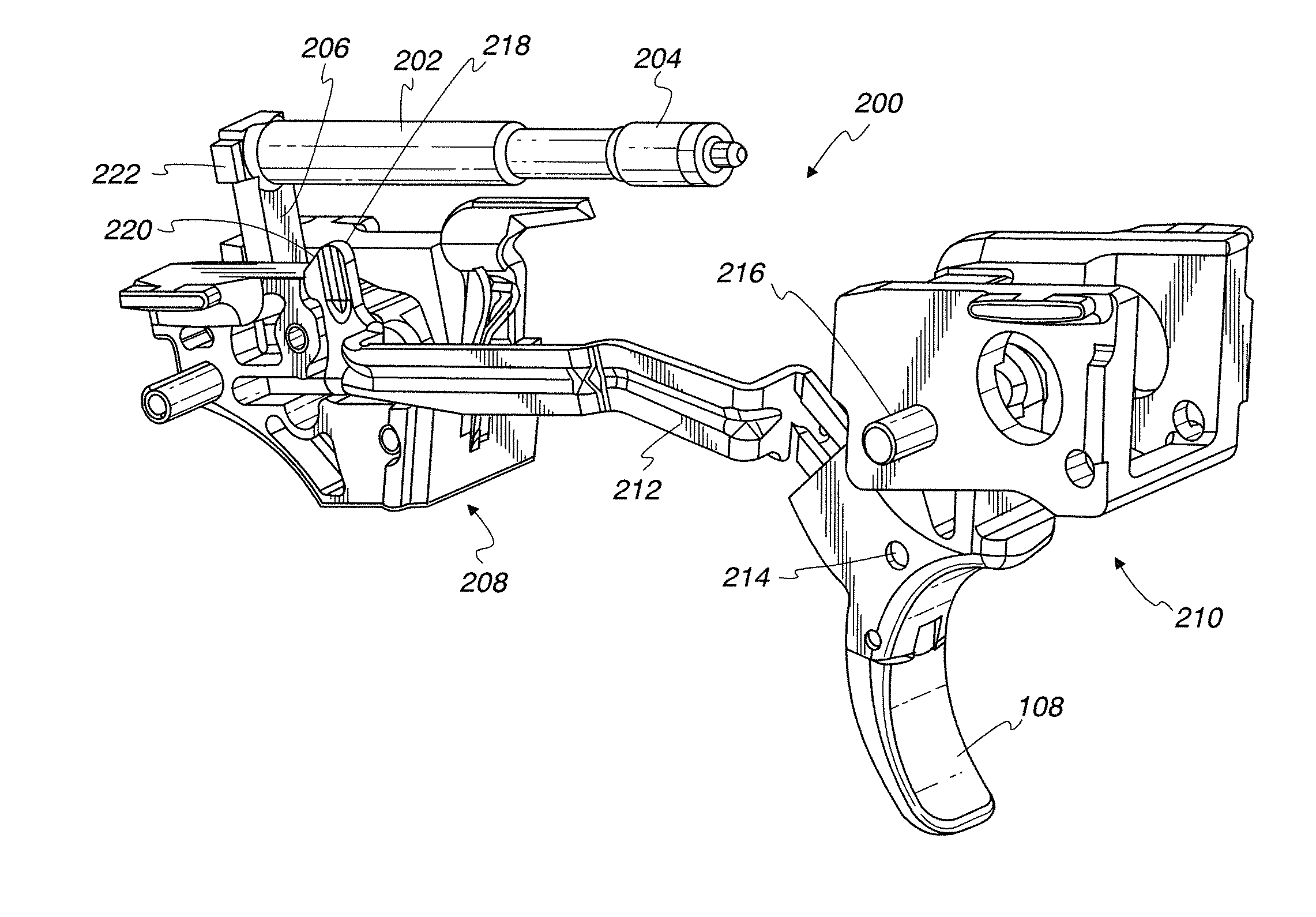
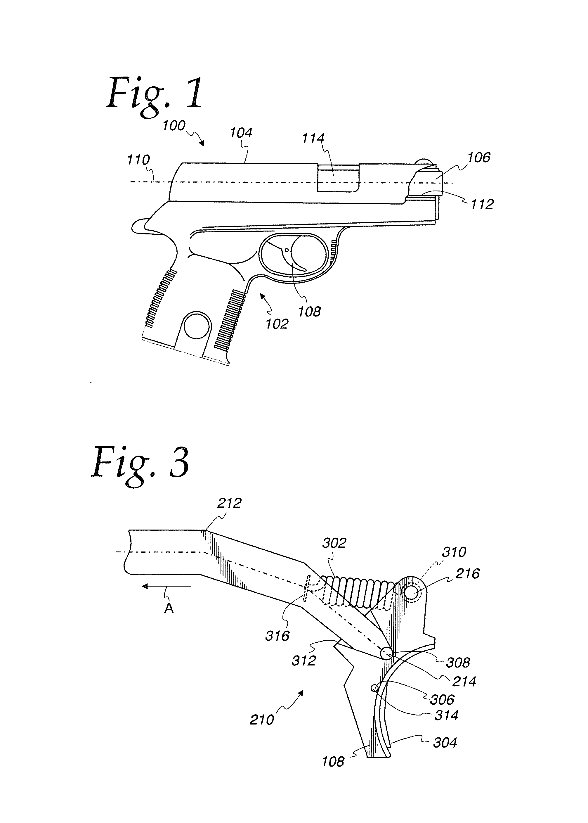
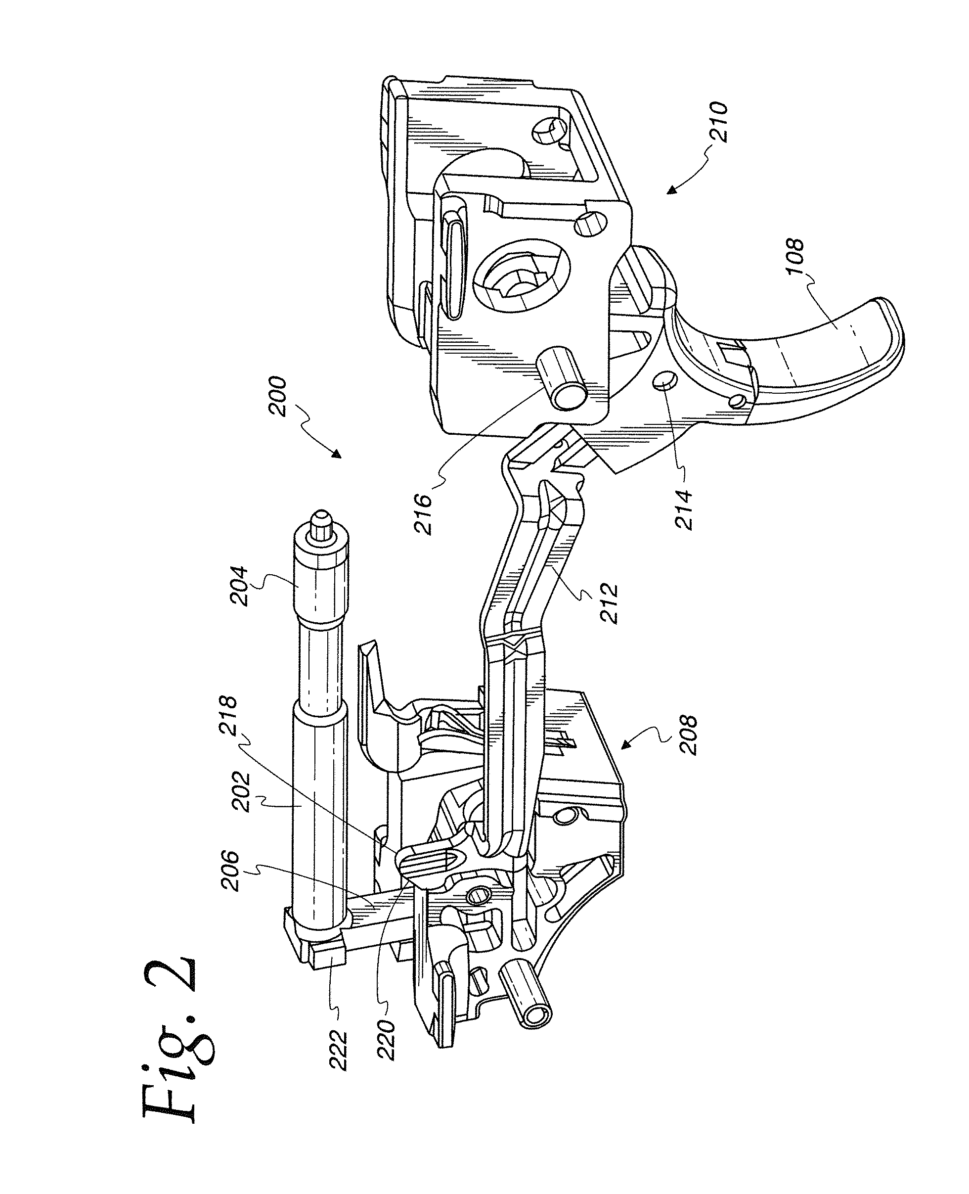
[0011]In yet another embodiment, a trigger for a firearm comprises a trigger face and a trigger connecting pin opening located near the top of the trigger and configured to receive a trigger connecting pin and to allow rotational movement of the trigger about the trigger connecting pin. The trigger also comprises a trigger bar pin opening located optionally between the trigger connecting pin opening and the vertical center of the trigger and configured to receive a trigger bar pin 214 and a rearward stop shoulder disposed on a rear surface of the trigger and located near and opposite the vertical center of the trigger face and configured to engage at least a portion of the body of the firearm to abate rearward rotational movement of the trigger about the trigger connecting pin. So configured, substantially no additional force is exerted on the trigger bar pin when a rearward force is applied to the trigger and the rearward stop shoulder is engaging the body of the firearm. Additionally, a force on the trigger connecting pin is greatly exceeded by a rearward force applied to the trigger when the rearward stop shoulder is engaging the body of the firearm.

Problems solved by technology

These travel distances, alone or in combination, can affect how a user grips the firearm and how their grip can change throughout the travel of the trigger, which can ultimately affect accuracy.
One such aspect of concern is that firearms often suffer from a phenomenon called “sear flutter.” This can render a firearm, and particularly semi-automatic firearms, useless until further action is taken to remedy the problem at the time of use of the firearm.
However, many of the components and factors affecting sear flutter also affect maximum trigger pull weight in an opposing manner.
Additionally, currently available configurations of firearm trigger and trigger assemblies can produce other problems.
One problem in particular is that trigger attachment pins can loosen and eventually cause the trigger to become detached during use, thereby rendering the firearm useless until the part is ultimately repaired.

Method used


Image

  • Firing mechanism for a firearm
  • Firing mechanism for a firearm
  • Firing mechanism for a firearm

Examples


Embodiment Construction

[0030]The following description is not to be taken in a limiting sense, but is made merely for the purpose of describing the general principles of exemplary embodiments. The scope of the invention should be determined with reference to the claims.

[0031]Reference throughout this specification to “one embodiment,”“an embodiment,” or similar language means that a particular feature, structure, or characteristic described in connection with the embodiment is included in at least one embodiment of the present invention. Thus, appearances of the phrases “in one embodiment,”“in an embodiment,” and similar language throughout this specification may, but do not necessarily, all refer to the same embodiment.

[0032]Furthermore, the described features, structures, or characteristics of the invention may be combined in any suitable manner in one or more embodiments. In the following description, numerous specific details are provided to provide a thorough understanding of embodiments of the inven...


PUM

PropertyMeasurementUnit
weightaaaaaaaaaa
weightaaaaaaaaaa
weightaaaaaaaaaa

Abstract

A firing mechanism for a firearm is provided for reducing maximum trigger pull weight attributable to a sear and for reducing trigger pre-travel and over-travel distances. By this, the likelihood of sear flutter phenomena is greatly reduced while also decreasing or maintaining maximum trigger pull weight. Also, hand movement during firing is reduced helping to increase accuracy.

Description

BACKGROUND OF THE INVENTION[0001]1. Field of the Invention[0002]The present invention relates generally to firearms, and more specifically to firing mechanisms for a firearm.[0003]2. Discussion of the Related Art[0004]Firearms, as are generally understood in the art, typically have a trigger with certain trigger characteristics. These characteristics may include a pre-travel distance, an engagement distance, an over-travel distance, and a reset distance. Additionally, while a trigger is traveling between these travel segments, trigger pull weights, or forces, are exerted in opposition to the general direction of travel of the trigger (except for a post-firing reset travel, wherein the force is generally in the direction of travel). Each travel segment may have a different trigger pull weight (i.e., level of force). This aids a user in determining by feel where a trigger is located within its general travel from a resting position through an engagement or firing position to a post-fi...

Claims


Application Information

Patent Timeline
Patent Type & Authority Applications(United States)
IPC IPC(8): F41A19/12F41A17/46B23P6/00F41A19/10
CPCF41A17/46F41A19/10F41A19/16Y10T29/4973F41A19/12F41A19/17F41A19/25
Inventor LEE, RANDALL M.
Owner APEX TACTICAL SPECIALTIES
Why Eureka
Try Eureka