
Optical parts casing and projector

a technology of optical parts and projectors, applied in the field of optical parts casings and projectors, can solve the problems of low cooling efficiency, reduced quantity of air used to cool respective portions, and insufficient air cooling

Inactive Publication Date: 2004-11-11
SEIKO EPSON CORP
View PDF4 Cites 18 Cited by
  • Summary
  • Abstract
  • Description
  • Claims
  • Application Information

AI Technical Summary

Benefits of technology

[0014] (1) The cooling fluid passing through the first passage cools the outer surface portion of the optical parts casing that the optical parts contact and to which the heat of the optical parts is transferred, and then enter into the inside of the optical parts casing from the holes formed in the outer surface portion to cool the optical modulator devices. In the present invention, since the outer surface portion is cooled directly by the cooling fluid passing through the first passage, such outer surface portion can be cooled effectively. As a result, the heat of the optical parts is readily transferred to the outer surface portion and thus radiation efficiencies of the optical parts can be enhanced.
[0065] According to this, because the flow regulating plates are provided in the passage, the uniformization of the flow rate of the cooling fluid flowing along the outer surface portion of the optical parts casing and / or the uniformization of the flow rate on the perpendicular cross section to the flowing direction can be achieved. As a result, the cooling fluid can be passed uniformly and effectively along the outer surface portion of the optical parts casing, and thus cooling efficiencies of the optical parts casing and the optical modulator devices, etc. can be enhanced.

Problems solved by technology

Therefore, there exists the problem that the warm air fails to cool sufficiently the bottom surface portion and thus a cooling efficiency is low.
Therefore, there exists the problem that a quantity of the air used to cool respective portions is reduced and thus the air fails to cool sufficiently both the bottom surface portion and the optical modulator device.
For example, in some cases it is difficult for the cooling fluid to enter from the second passage according to the positions of the holes formed in the outer surface portion.
Also, when a plurality of second passages are formed, the fan may be connected to the passages respectively, but a number of fans are needed and thus a cost is increased.
Also, a large space in which a number of fans are installed is required.
For example, in some cases it is difficult for the cooling fluid to enter from the second passage according to the positions of the holes formed in the outer surface portion.
Also, when a plurality of second passages are formed, the fan may be connected to the passages respectively, but a number of fans are needed and thus a cost is increased.
Also, a wide space in which a number of fans are installed is required.
For example, in some cases it is difficult for the cooling fluid to enter from the second passage according to the positions of the holes formed in the outer surface portion.
Also, when a plurality of second passages are formed, the fan may be connected to the passages respectively, but a number of fans are needed and thus a cost is increased.
Also, a large space in which a number of fans are installed is required.

Method used


Image

  • Optical parts casing and projector
  • Optical parts casing and projector
  • Optical parts casing and projector

Examples


second embodiment

[0217] Next, the present invention will be explained with reference to FIG. 11 hereunder. In this case, in following explanations, the same reference symbols are affixed to the same portions as those already explained and their explanations will be omitted herein.

[0218] The present embodiment is different from the above embodiment in a rib structure of the duct provided to the bottom surface portion 512B of the optical parts casing. In other words, an optical parts casing 5B of the present embodiment has a duct 7 that is different from that in the above embodiment, but other respects are similar to the optical parts casing 5A in the above embodiment. The duct 7 in the present embodiment has a rib (outer peripheral wall) 71. This rib 71 has the first rib 611 almost similar to the above embodiment, and a second rib (second outer peripheral wall) 712 provided on the inside of the first rib (first outer peripheral wall) 611. In the present embodiment, the duct 7 and the intake fan 31 ac...

first embodiment

[0224] Meanwhile, the other part of the cooling air introduced into the opening port of the duct 7 is introduced into the second passage 7B. A part of this cooling air is at first introduced into the hole 515G formed at the position that corresponds to the liquid crystal panel 441G, and the remaining cooling air is introduced into the hole 515B formed at the position that corresponds to the liquid crystal panel 441B. That is, the cooling air flowing through the second passage 7B with the above, like the first embodiment, the cooling air introduced into the holes 515R, 515G, 515B cools the optical device 44.

[0225] According to the present embodiment, the same advantages as those recited in (1-1), (1-2), (1-4) to (1-6) of the first embodiment can be achieved, and in addition following advantages can be achieved.

[0226] (2-1) The second rib 712 does not surround the lower portion of the cross dichroic prism 444 of the optical device 44, and an area of the bottom surface portion 512B sur...

third embodiment

3. THIRD EMBODIMENT

[0228] Next, a third embodiment of the present invention will be explained with reference to FIG. 12 hereunder.

[0229] In the first embodiment and the second embodiment, a single intake fan 31 for sucking the cooling air is provided. In the present embodiment, two intake fans are provided.

[0230] One intake fan 31A of the intake fan 31 is arranged in front of the hole 515B corresponding to the liquid crystal panel 441B (on the projection lens 46 side (the left side in FIG. 12)), while the other intake fan 31B is arranged in front of the hole 515R corresponding to the liquid crystal panel 441R (on the projection side (the projection lens 46 side)).

[0231] An optical parts casing 5C in the present embodiment has a duct 8 whose shape is different from the above embodiments, but other respects are similar to those of the optical parts casing 5A in the above embodiments.

[0232] The duct 8 has two opening ports connected to the intake fans 31A, 31B respectively, and a rib (...


PUM


Abstract

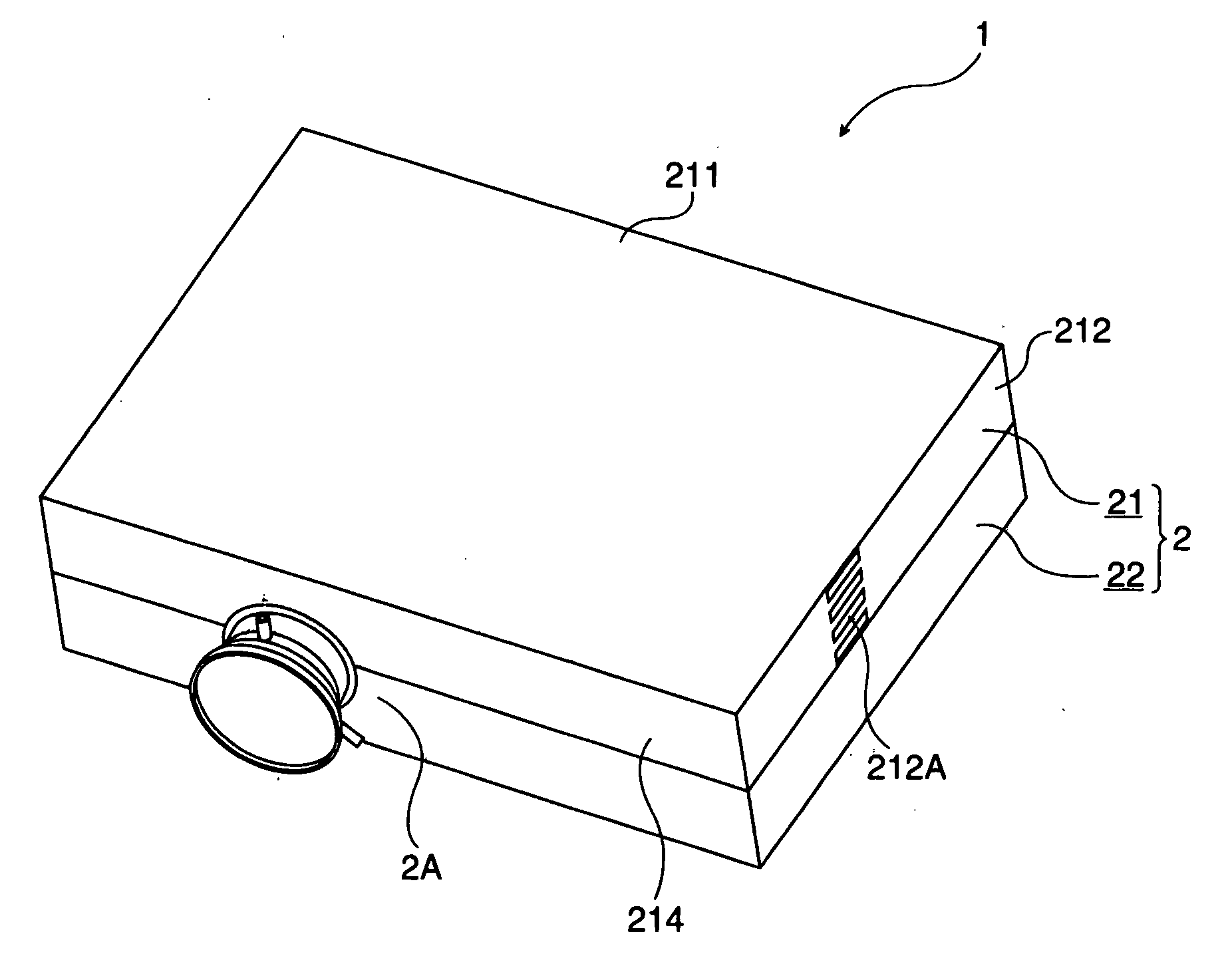
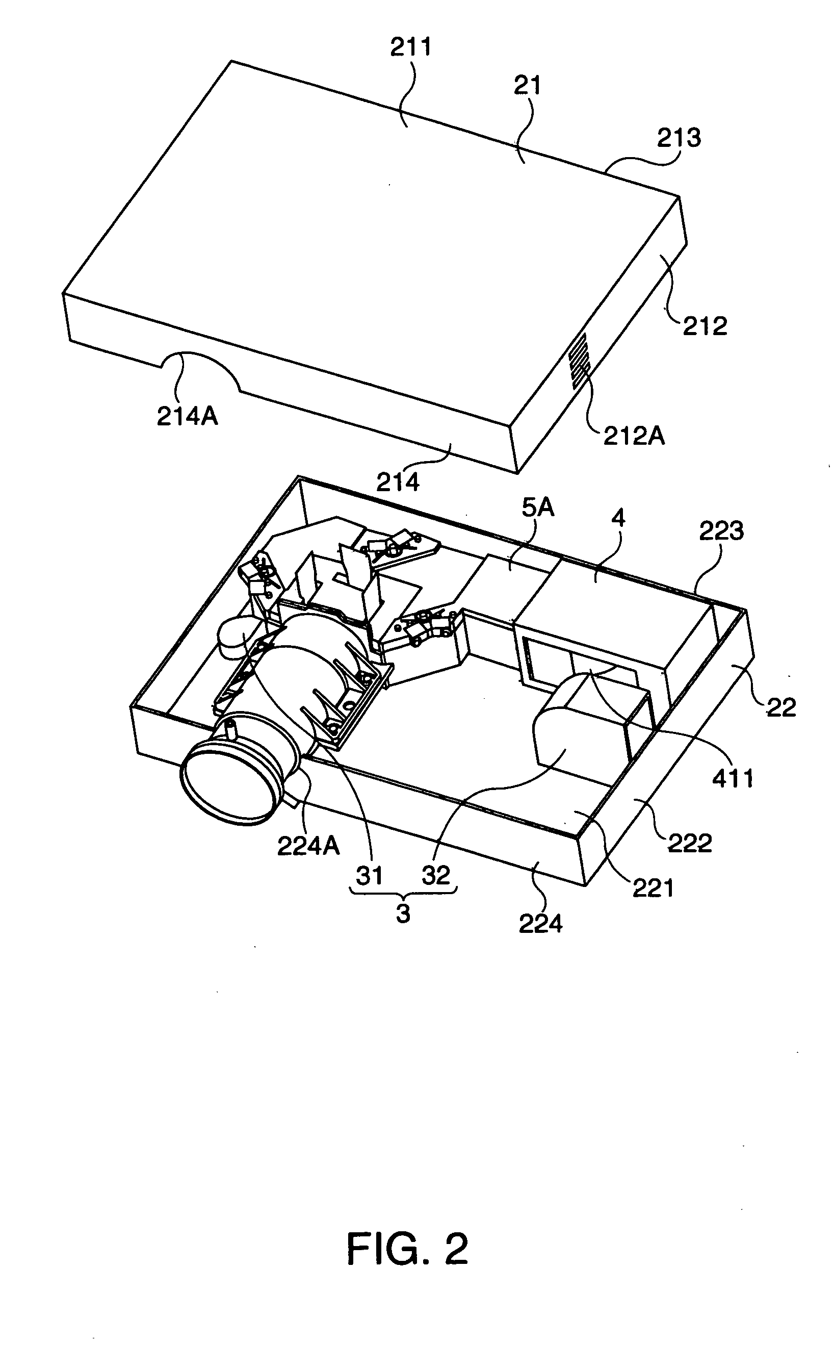
Heat of optical devices is transferred to a bottom surface portion 512B of an optical parts housing portion 512 of an optical parts casing 5A. A duct 6 is formed on the bottom surface portion 512B. A cooling air passing through a first passage 6A cools the bottom surface portion 512B, and then is supplied to a hole 515R to cool a liquid crystal panel 441R, etc. The cooling air passing through a second passage 6B of the duct 6 is introduced into holes 515B, 515G to cool the liquid crystal panels 441B, 441G. Accordingly, the optical parts casing projector capable of cooling sufficiently the optical modulator devices and other parts, e.g., the bottom surface portion, etc. of the optical parts casing.

Description

[0001] The present invention relates to an optical parts casing and a projector.[0002] The present invention can be utilized as a projector that is widely utilized in a multimedia presentation in a conference, an academic conference, an exhibition, and so on.RELATED ART[0003] In the prior art, the projector for emitting a luminous flux from a light source to uniformize an intensity in an irradiated plane by an illumination optical system, then separating the luminous flux into three color lights of a red light, a green light, and a blue light by a color separation optical system, then modulating the color lights by an optical modulator device every color light, then synthesizing the color lights by a color synthesis optical system, and then enlarging and projecting a color image from a projection optical system is known.[0004] The optical systems of such projector have a plurality of optical parts respectively. For instance, the illumination optical system has an integrator lens for...

Claims


Application Information

Patent Timeline
IPC IPC(8): G03B21/16H04N5/74
CPCG03B21/16H04N9/3141H04N9/3144
Inventor YANAGISAWA, YOSHIYUKIABE, HIROSHI
Owner SEIKO EPSON CORP
Learn More