This helps you quickly interpret patents by identifying the three key elements:
Problems solved by technology
Method used
Benefits of technology
Benefits of technology
The patent describes a rotating electric machine with improved cooling performance that increases output. This is achieved by setting an inner gap through which coolant flows at a faster rate, using twisted portions to guide coolant and improve cooling of the stator and coil, and by sandwiching a temperature sensing element between bridging parts to accurately sense the temperature and prevent protrusion. The coolant flow rate is controlled based on the temperature sensor readings to further improve cooling performance.
Problems solved by technology
However, during operation of the motor, both the outer and inner stators generate heat.
Consequently, it is difficult to supply coolant to the inner stator; thus, it is difficult to dissipate the heat generated by the inner stator.
Method used
Image
Click on the blue label to locate the original text in one second.
Reading with bidirectional positioning of images and text.
Examples
first embodiment
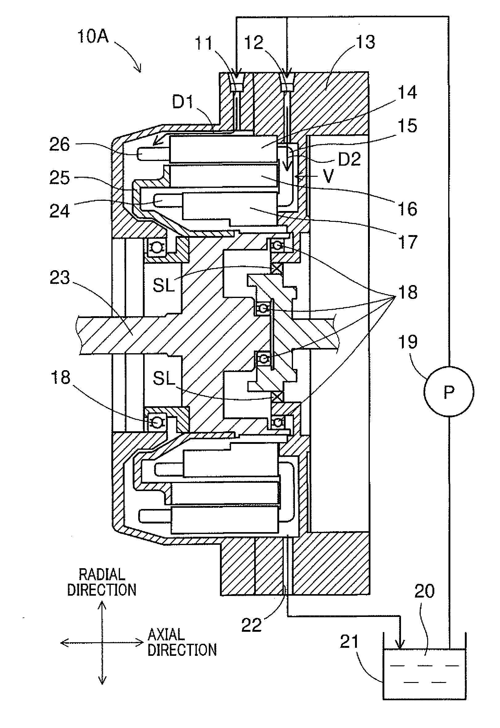
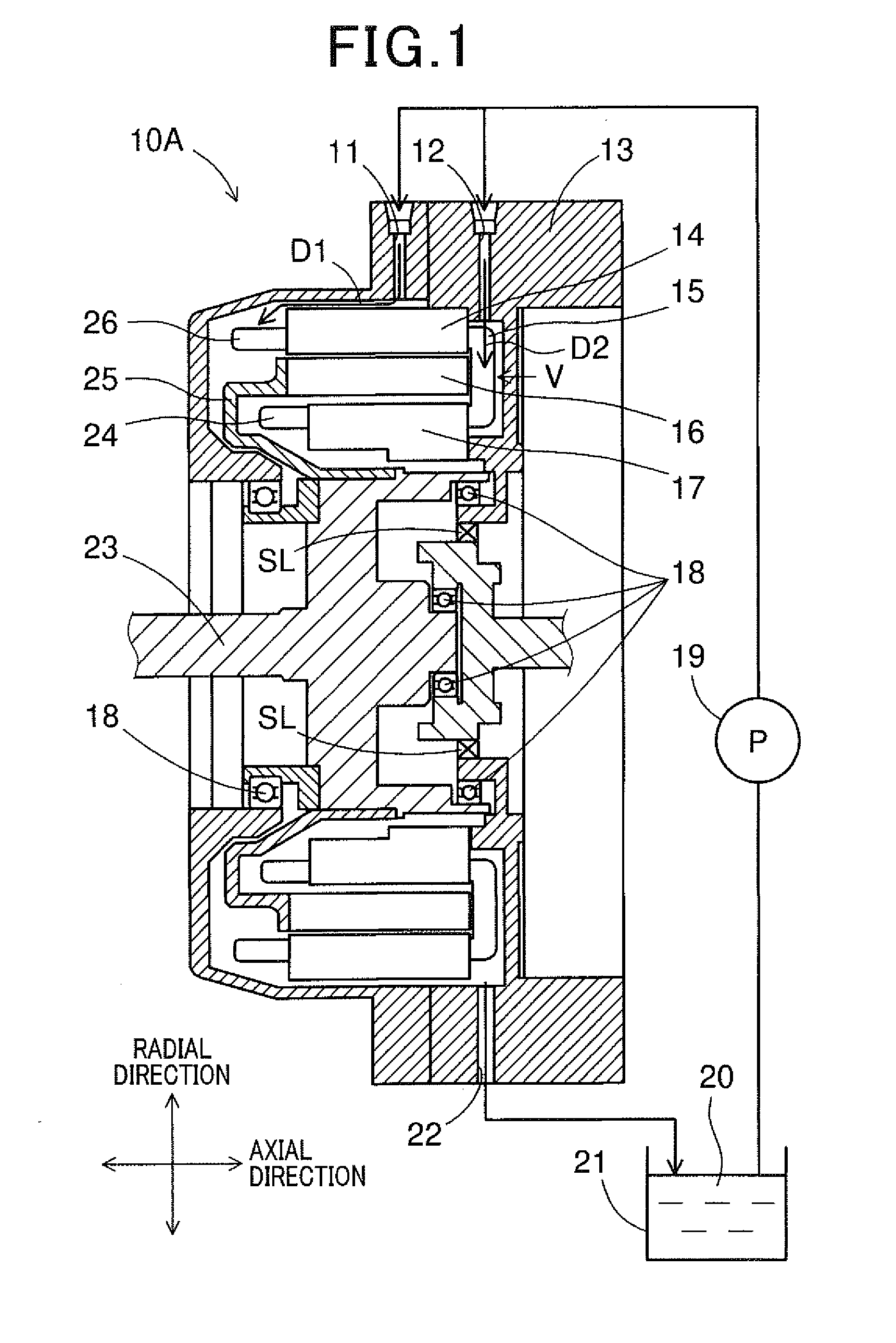
[0044]FIG. 1 shows the overall configuration of a double-stator rotating electric machine 10A according to a first embodiment.
[0045]In this embodiment, the rotating electric machine 10A is configured as a motor-generator that selectively functions either as an electric motor or as an electric generator.
[0046]As shown in FIG. 1, the rotating electric machine 10A includes a housing 13, an outer stator 14, a rotor 16, an inner stator 17, bearings 18, a rotating shaft 23 and a disc 25.
[0047]The housing 13 may have any shape suitable for receiving the outer stator 14, the rotor 16, the inner stator 17, the rotating shaft 23 and the disc 25 therein.
[0048]In the housing 13, there are provided the bearings 18 via which the rotating shaft 23 is rotatably supported by the housing 13. In addition, the rotating shaft 23 may have any shape suitable for rotation.
[0049]Coolant 20, which is drawn up by a pump 19 from a coolant reservoir 21, flows down in the housing 13. The coolant 20 in the housin...
second embodiment
[0144]FIG. 23 shows the overall configuration of a double-stator rotating electric machine 10B according to a second embodiment.
[0145]As seen from FIG. 23, the configuration of the double-stator rotating electric machine 10B according to the present embodiment is almost identical to that of the double-stator rotating electric machine 10A according to the first embodiment (see FIG. 1). Accordingly, only the differences therebetween will be described hereinafter.
[0146]In the first embodiment, the rotating electric machine 10A includes only the first and second coolant introduction portions 11 and 12 formed in the housing 13 (see FIG. 1).
[0147]In comparison, in the present embodiment, as shown in FIG. 23, the rotating electric machine 10B further includes a third coolant introduction portion 50 in addition to the first and second coolant introduction portions 11 and 12. The third coolant introduction portion 50 is formed in the rotating shaft 23, unlike the first and second coolant int...
PUM
Abstract
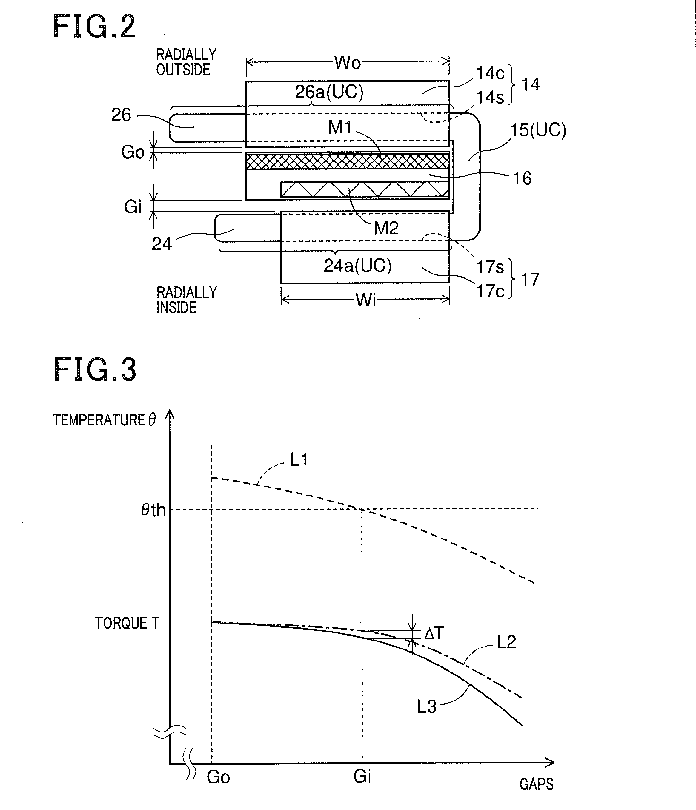
A double-stator rotating electric machine includes a rotor, an outer stator disposed radially outside the rotor with an outer gap formed therebetween, and an inner stator disposed radially inside the rotor with an inner gap formed therebetween. The outer stator has an outer multi-phase coil wound thereon, and the inner stator has an inner multi-phase coil wound thereon. Moreover, the inner gap formed between the inner stator and the rotor is set to be larger than the outer gap formed between the outer stator and the rotor.
Description
CROSS-REFERENCE TO RELATED APPLICATION[0001]This application is based on and claims priority from Japanese Patent Application No. 2014-161310 filed on Aug. 7, 2014, the content of which is hereby incorporated by reference in its entirety into this application.BACKGROUND[0002]1 Technical Field[0003]The present invention relates to double-stator rotating electric machines which include a rotor, an outer stator disposed radially outside the rotor, and an inner stator disposed radially inside the rotor.[0004]2 Description of Related Art[0005]Japanese Patent Application Publication No. JP2007282331A discloses a double-stator electric motor. The motor includes a rotor, an outer stator disposed radially outside the rotor, and an inner stator disposed radially inside the rotor. The rotor includes an annular rotor core, a plurality of outer permanent magnets and a plurality of inner permanent magnets. The rotor core has a plurality of fitting holes and a plurality of protrusions. The fitting...
Claims
Application Information
Patent Timeline
Application Date:The date an application was filed.
Publication Date:The date a patent or application was officially published.
First Publication Date:The earliest publication date of a patent with the same application number.
Issue Date:Publication date of the patent grant document.
PCT Entry Date:The Entry date of PCT National Phase.
Estimated Expiry Date:The statutory expiry date of a patent right according to the Patent Law, and it is the longest term of protection that the patent right can achieve without the termination of the patent right due to other reasons(Term extension factor has been taken into account ).
Invalid Date:Actual expiry date is based on effective date or publication date of legal transaction data of invalid patent.

