Systems and Methods for De-Icing a Gas Turbine Engine Inlet Screen and Dehumidifying Inlet Air Filters

a gas turbine engine and inlet filter technology, applied in the field of gas turbine engines, can solve the problems of ice buildup on the turbine inlet filter house components, combustion turbine performance loss or even shut down, and ice buildup

Inactive Publication Date: 2013-12-26
GENERAL ELECTRIC CO
View PDF10 Cites 47 Cited by
  • Summary
  • Abstract
  • Description
  • Claims
  • Application Information

AI Technical Summary

Benefits of technology

[0009]The disclosure provides a solution to the problem of preventing ice build-up on the gas turbine engine inlet screens, without significant performance loss.

Problems solved by technology

Operation during cold ambient temperature and high humidity conditions often causes ice to build up on the turbine inlet filter house components.
Frequently this ice build-up on air filtration elements (bird screens, moisture separators, coalescer filters, and filtration modules) is severe enough to restrict air flow and to increase the inlet air pressure drop across the filter house thus leading to combustion turbine performance loss or even shut down.
Precipitating icing forms when water ingested as liquid or solid at a temperature near or below freezing (wet snow, freezing rain, etc.) adheres to most exposed surfaces, causing ice buildup.
Also, ice formation occurs when saturated cooled air comes in contact with colder filter house surfaces.
This permits enough hot exhaust gases to be constantly recirculated to the inlet to maintain turbine inlet air temperature at a minimum of +40° F. This approach has the disadvantage of increasing the pressure at the turbine exhaust, thereby negatively impacting the performance of the gas turbine engine.
This approach increases the capital-costs and may negatively impact production efficiency through the operating year due to the additional air flow restriction (pressure drop) imposed by, for example, the heating coils.

Method used


Image

  • Systems and Methods for De-Icing a Gas Turbine Engine Inlet Screen and Dehumidifying Inlet Air Filters
  • Systems and Methods for De-Icing a Gas Turbine Engine Inlet Screen and Dehumidifying Inlet Air Filters
  • Systems and Methods for De-Icing a Gas Turbine Engine Inlet Screen and Dehumidifying Inlet Air Filters

Examples


Embodiment Construction

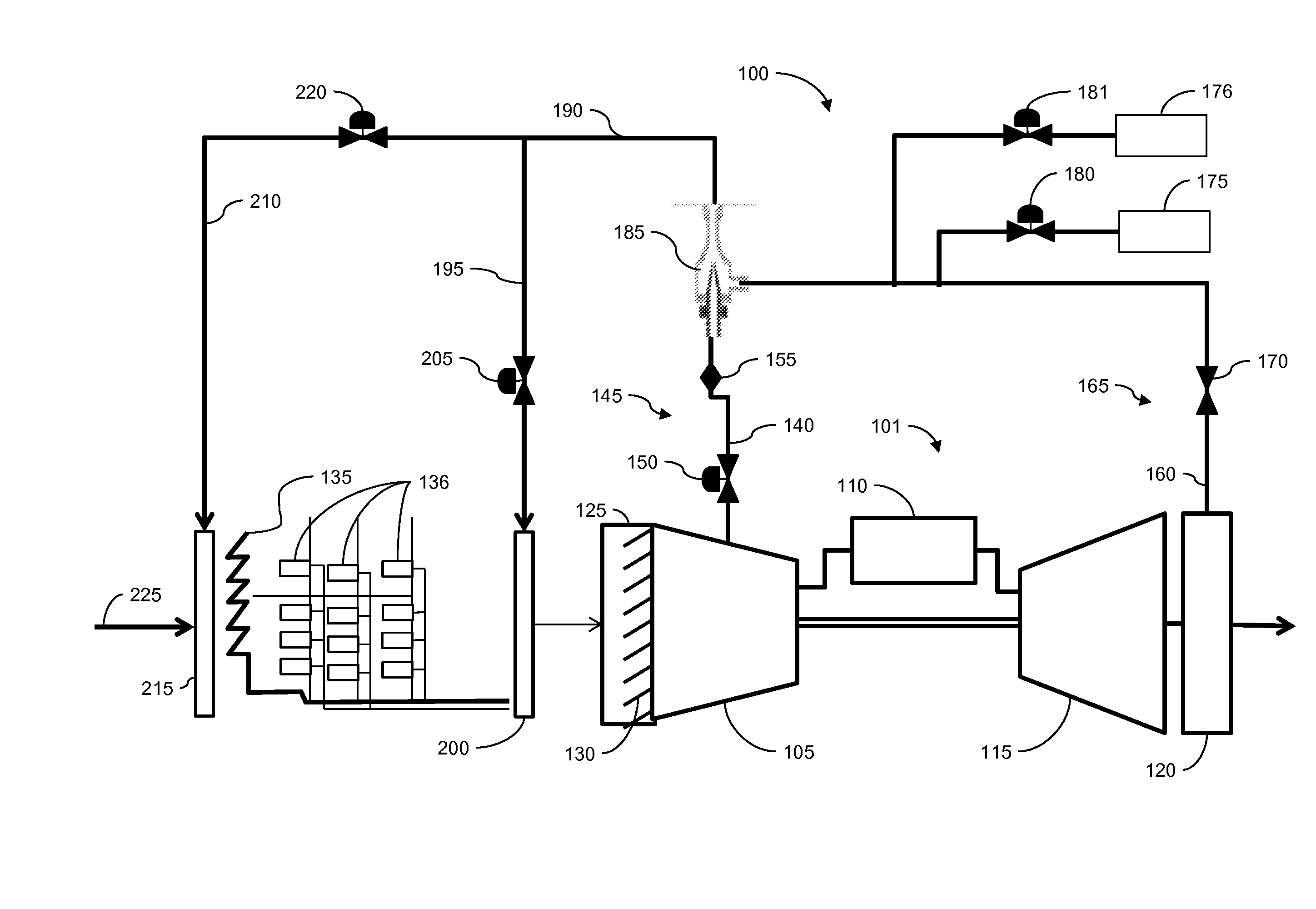
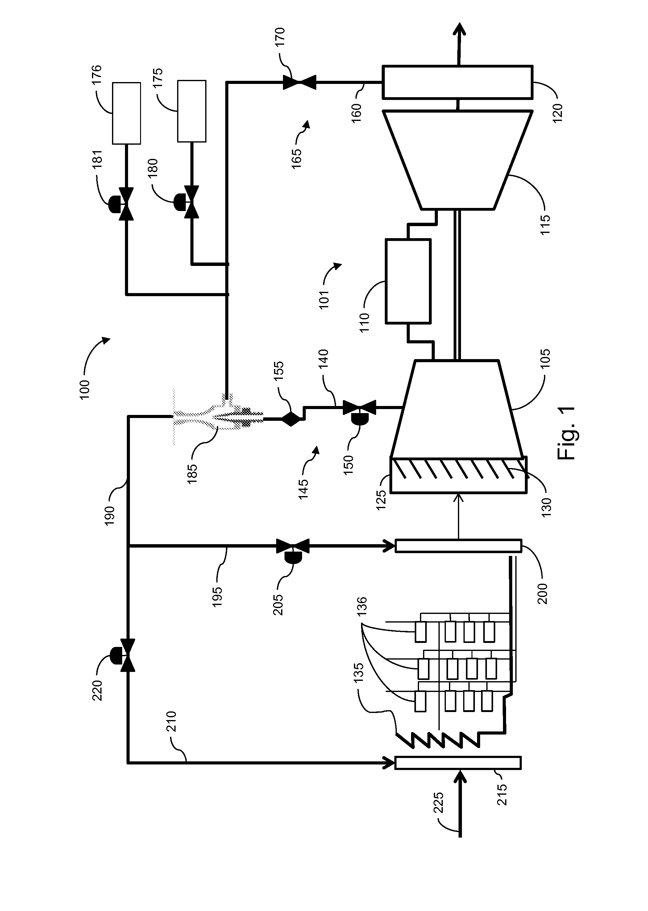
[0020]Illustrated in FIG. 1 is an embodiment of a gas turbine system 100 with an inlet screen de-icing capability. The gas turbine system 100 may include one or more gas turbine engine(s) 101. Each gas turbine engine 101 includes a compressor 105 that compresses an incoming flow of air. The compressor 105 delivers the compressed flow of air to a combustion subsystem 110 where the compressed flow of air mixes with a compressed flow of fuel and the mixture is ignited to create a flow of combustion gases. The flow of combustion gases is in turn delivered to a turbine 115 and drives the turbine 115 to produce mechanical work. The mechanical work produced in the turbine 115 drives the compressor 105 and an external load such as, for example, an electrical generator. The flow of combustion gases may be exhausted via an exhaust subsystem 120 to a stack or otherwise disposed.

[0021]The gas turbine engine 101 may include a compressor inlet subsystem 125 with an articulated inlet guide vane as...


PUM


Abstract

A system for de-icing a gas turbine engine is provided. A manifold is coupled to an inlet screen. A first conduit is coupled to a stage of the compressor and a first input of a mixing component. A second conduit is coupled to the exhaust and a second input of the mixing component. The second conduit being adapted to extract exhaust gases without increasing the pressure at the exhaust. A third conduit is coupled to the output of the mixing component and the manifold. A method for de-icing a gas turbine engine inlet screen includes determining a current temperature at the inlet screen, and determining a desired temperature at the inlet screen. If the current temperature at the inlet screen is less than the desired temperature at the inlet screen first flow rate of an air-exhaust mixture necessary to achieve the desired inlet screen temperature is calculated. The method also includes extracting an amount of exhaust gas from a turbine exhaust subsystem without increasing a pressure at the turbine exhaust subsystem, extracting an amount of air from a compressor stage, and mixing the amount of exhaust gas with the amount of air to generate an air-exhaust mixture that is conveyed to the inlet screen.

Description

CROSS-REFERENCE TO RELATED APPLICATIONS[0001]This application is a continuation-in-part of U.S. Ser. No. 13 / 303,852 filed Nov. 23, 2011.TECHNICAL FIELD[0002]The subject matter disclosed herein generally relates to gas turbine engines and more particularly to methods and systems to prevent icing of gas turbine engine inlet screens.BACKGROUND[0003]Gas turbine engines typically include a compressor for compressing incoming air, a combustor for mixing fuel with the compressed air and for igniting a fuel / air mixture to form a high temperature gas stream, and a turbine section driven by the high temperature gas stream.[0004]Gas turbine engines are utilized globally for electric power generation or as mechanical drives for operating pumps and compressors, under a variety of climatic conditions. Operation during cold ambient temperature and high humidity conditions often causes ice to build up on the turbine inlet filter house components. Frequently this ice build-up on air filtration eleme...

Claims


Application Information

Patent Timeline
Patent Type & Authority Applications(United States)
IPC IPC(8): F02C7/047
CPCF02C7/047F02C6/08F02C6/18F02C7/055
Inventor EKANAYAKE, SANJISCIPIO, ALSTON ILFORDDAVIS, DALE J.PASTRANA, RYAN MARGATE
Owner GENERAL ELECTRIC CO
Why Eureka
Try Eureka