Robot hand

a robot hand and hand-held technology, applied in the field of robot hands, can solve the problems of misalignment of the work unit mounted to the mounting surface of the robot hand, and the inability to place the work unit into the cassette,

Active Publication Date: 2013-12-26
DISCO CORP
View PDF5 Cites 11 Cited by
  • Summary
  • Abstract
  • Description
  • Claims
  • Application Information

AI Technical Summary

Benefits of technology

[0008]In light of the foregoing, it is an object of the present invention to provide a robot hand that can place a work unit into a cassette even if an outer perimeter portion of the work unit comes into contact with an inner wall of the cassette.
[0009]In accordance with an aspect of the present invention, there is provided a robot hand that is fitted to an arm of a robot for placing a work unit into a cassette. The work unit includes an annular frame, an adhesive tape and a plate-shaped work. The annular frame has an opening portion, a pair of first positioning surfaces extending parallel to each other with the opening portion sandwiched therebetween, and a pair of second positioning surfaces extending parallel to each other in a direction orthogonal to the first positioning surfaces with the opening portion sandwiched therebetween. An outer perimeter portion of the adhesive tape is affixed to the annular frame. The plate-shaped work is affixed to the adhesive tape. The robot hand includes a mounting surface, a pair of anti-fall hooks and a pair of support sections. The work unit is mounted to the mounting surface with some freedom of horizontal movement allowed for the work unit. Each of the anti-fall hooks is formed at one edge portion of the mounting surface to support a front edge portion of the work unit mounted to the mounting surface, thus preventing the work unit from falling off the mounting surface. Each of the support sections is provided at an other edge portion of the mounting surface opposite to the anti-fall hooks to support a rear edge portion of the work unit. If the annular frame collides with the cassette when the robot is activated to place the work unit, mounted to the mounting surface of the robot hand, into the cassette, the robot hand permits the rear edge portion of the work unit to come into contact with one of the support sections, thus allowing the work unit to be rotated on the mounting surface about the support section in contact with the rear edge portion as a fulcrum and allowing the work unit to be placed into the cassette.
[0010]The robot hand according to the present invention includes the pair of anti-fall hooks and the pair of support sections. The anti-fall hooks support the front edge portion of the work unit mounted to the mounting surface, thus preventing the work unit from falling off the mounting surface. The support sections are provided near a fitting section adapted to fit the robot hand to the arm of the robot, thus supporting the rear edge portion of the work unit. This makes it possible, if the outer perimeter portion of the work unit mounted to the mounting surface collides with the cassette during placement of the work unit into the cassette, to bring the support section into contact with the rear edge portion of the work unit and rotate the work unit on the mounting surface about the contact point as a fulcrum. As a result, the positional misalignment of the work unit is corrected on the mounting surface of the robot hand. This ensures positive placement of the work unit into the cassette even if the outer perimeter portion of the work unit is in contact with an inner wall of the cassette.
[0011]Further, the pair of support sections are provided near the fitting section. This makes it possible for one of the support sections, i.e., the one appropriate for the positional misalignment of the work unit on the mounting surface, to support the rear edge portion of the work unit, thus allowing the work unit to be rotated on the mounting surface about the point where the same unit is supported by the support section as a fulcrum.

Problems solved by technology

However, the work unit mounted to the mounting surface of the robot hand may be misaligned in a direction of rotation of the work unit about its center in some cases.
If the robot hand attempts to place the work unit into the cassette in this condition, an outer perimeter portion of the work unit comes into contact with an inner wall of the cassette, thus making it impossible to place the work unit into the cassette.

Method used


Image

  • Robot hand
  • Robot hand
  • Robot hand

Examples


Embodiment Construction

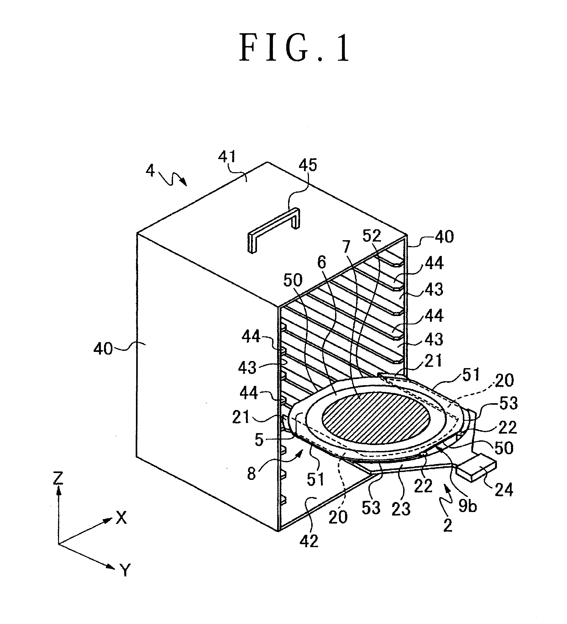
[0018]A cassette 4 shown in FIG. 1 can accommodate a plurality of workpieces to be worked on such as plate-shaped works. The cassette 4 is formed in the shape of a box with a pair of side plates 40 that are installed upright in a z-axis direction, a top plate 41 connected to upper edge portions of the pair of side plates 40, and a bottom plate 42 connected to lower edge portions of the pair of side plates 40. A plurality of pairs of accommodating sections 44 are provided on inner walls 43 of the pair of side plates 40. The accommodating sections 44 are provided at predetermined spacings in the z-axis direction and protrude in a horizontal direction. Further, a grip 45 adapted to transport the cassette 4 is provided on an upper surface of the top plate 41.

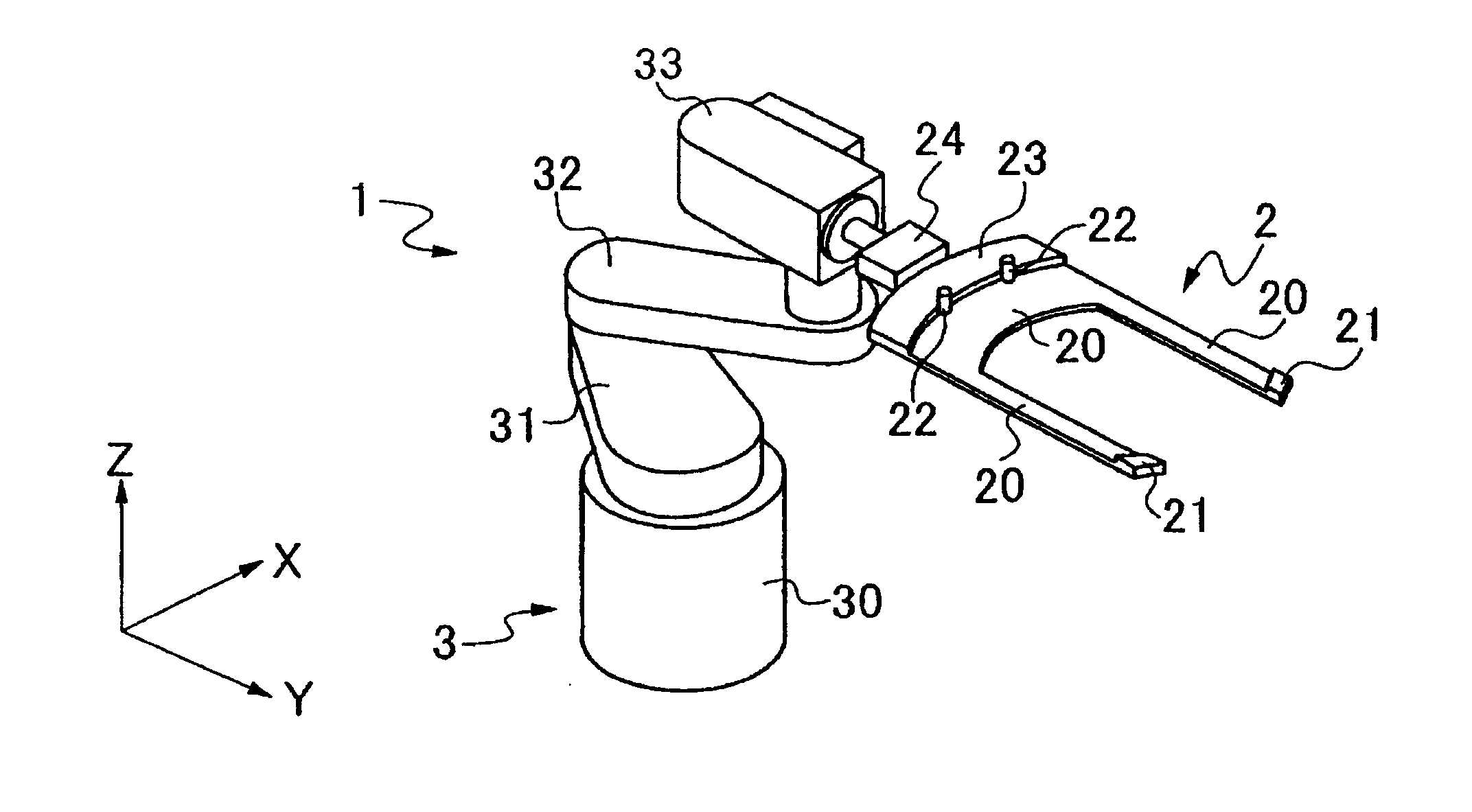
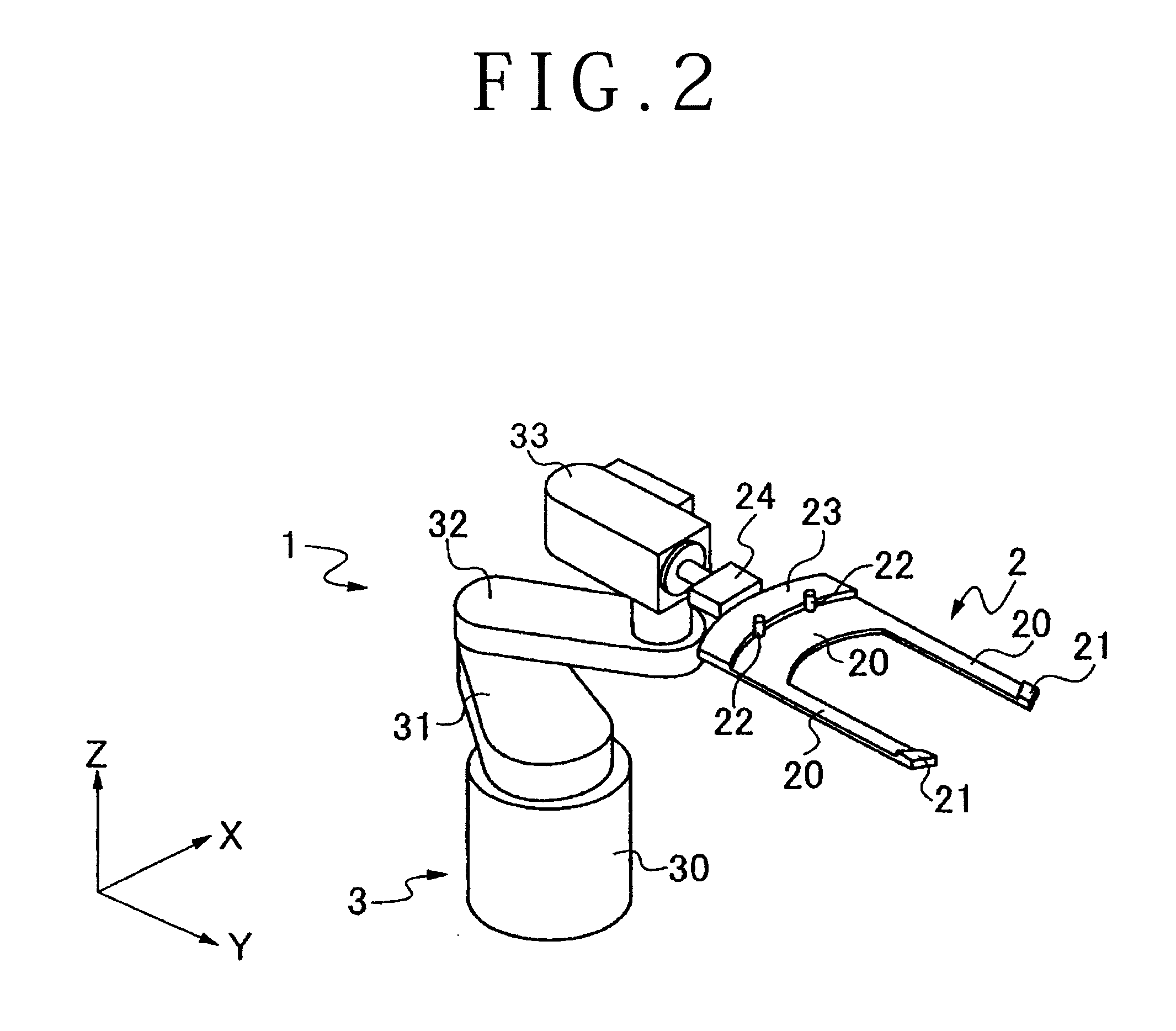
[0019]A work unit 8 is placed into each pair of accommodating sections 44 by a robot hand 2. The work unit 8 is formed by affixing a plate-shaped work 7 to an annular frame 5 to which an adhesive tape 6 is affixed. The spacing betwe...


PUM


Abstract

A robot hand includes a mounting surface to which a work unit is mounted with some freedom of horizontal movement. A pair of anti-fall hooks is formed at a tip portion of the mounting surface to support a front edge portion of the work unit so as to prevent the work unit from falling off the mounting surface. A pair of support section is provided at a rear edge portion of the mounting surface to support a rear edge portion of the work unit. If, during placement of the work unit into a cassette, the work unit collides with the cassette, the work unit comes into contact with one of the support sections, and the work unit is rotated on the mounting surface about the contact point as a fulcrum so as to correct the misalignment of the work unit.

Description

BACKGROUND OF THE INVENTION[0001]1. Field of the Invention[0002]The present invention relates to a robot hand for transporting a work unit that includes a plate-shaped work supported by an annular frame via an adhesive tape.[0003]2. Description of the Related Art[0004]When a plate-shaped work is processed by a processor, an adhesive tape is affixed to one side of an annular frame whose central portion is open first. Then, the plate-shaped work is affixed to an adhesive side of the adhesive tape exposed from the opening portion of the annular frame, thus forming a work unit. A processor for processing a plate-shaped work making up such a work unit includes at least a cassette, robot hand, temporary storage table, processing table, processing means and cleaning means. The cassette accommodates the work unit. The robot hand unloads the work unit from and loads it onto the cassette. The temporary storage table temporarily stores the work unit. The processing table holds the work unit. T...

Claims


Application Information

Patent Timeline
Patent Type & Authority Applications(United States)
IPC IPC(8): B25J15/00
CPCB25J15/008H01L21/68707Y10S414/137H01L21/67265H01L21/67766
Inventor YAMANAKA, SATOSHI
Owner DISCO CORP
Why Eureka
Try Eureka