

Repeater fiber-coax units
- Summary
- Abstract
- Description
- Claims
- Application Information
AI Technical Summary
Benefits of technology
Problems solved by technology
Method used
Image

Examples
Embodiment Construction
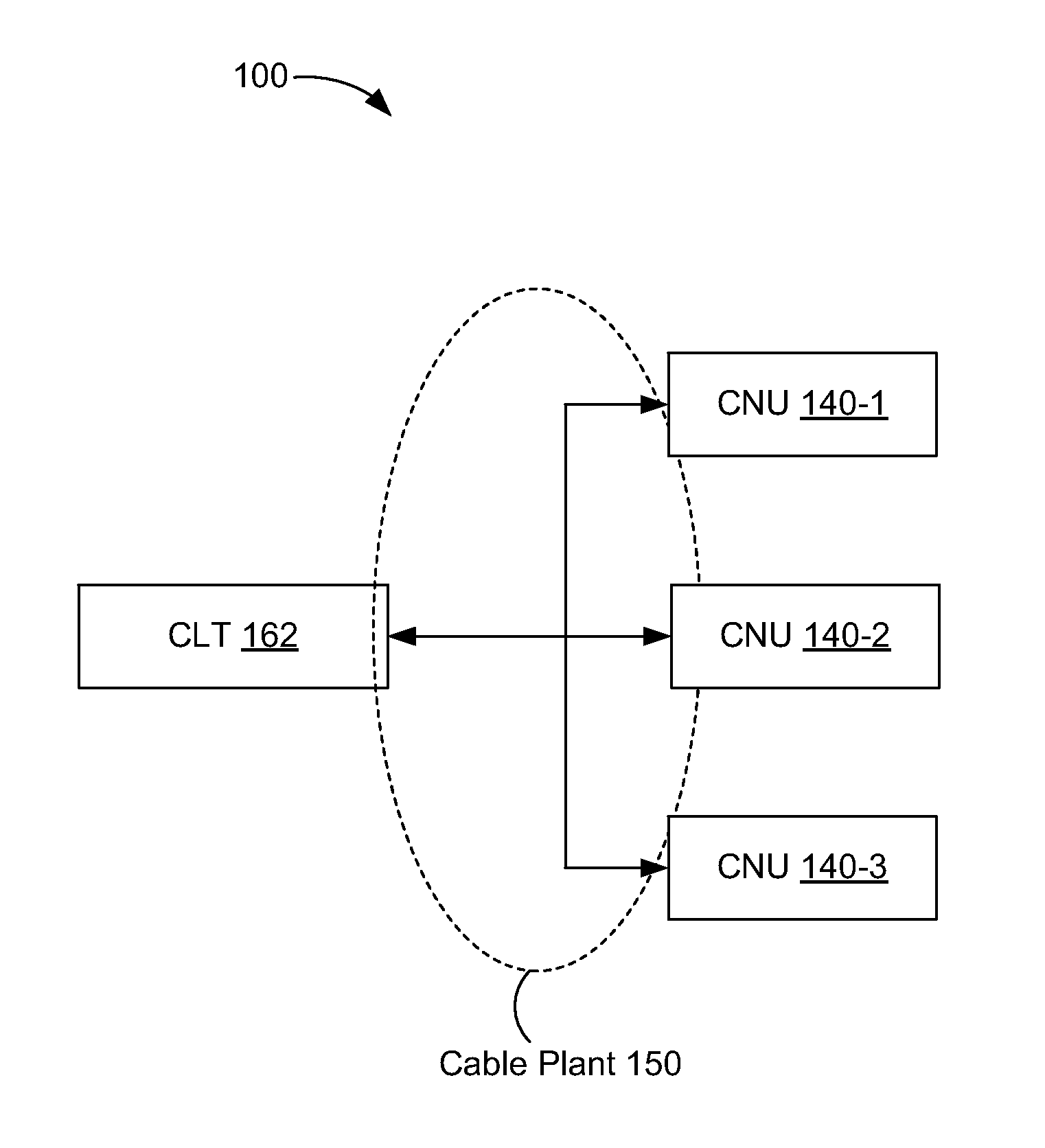
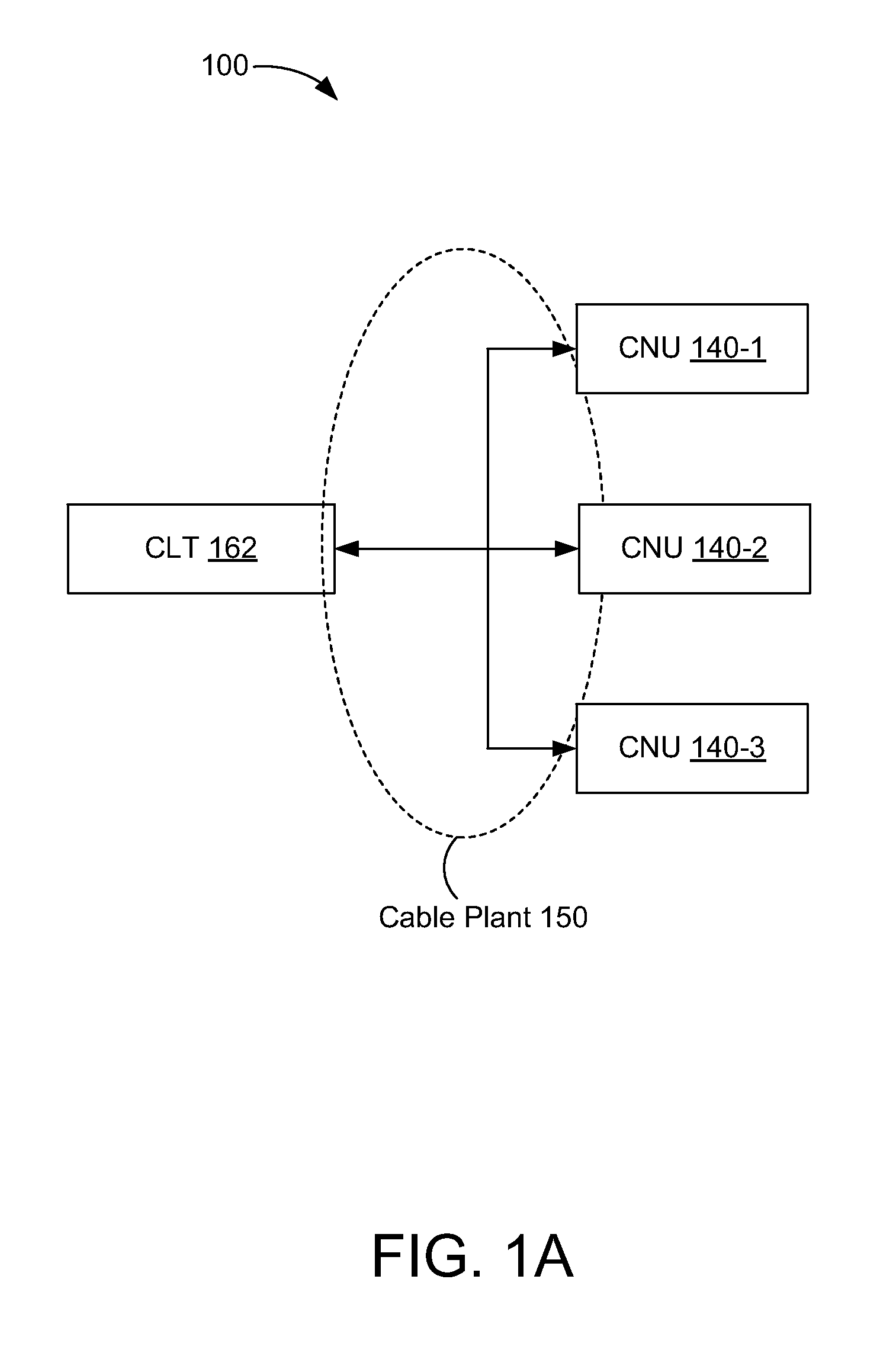
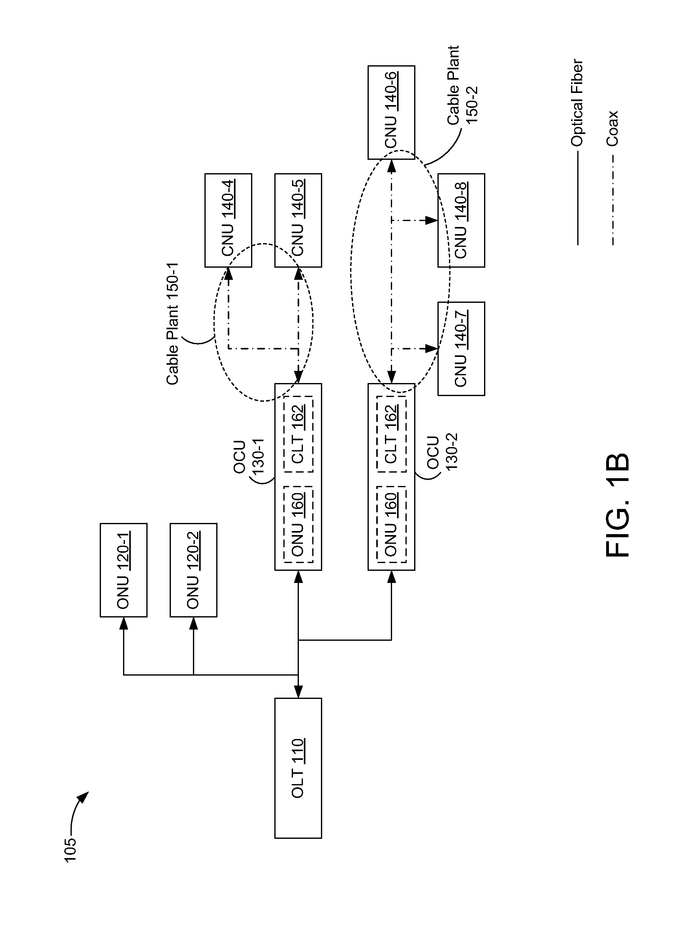
[0029]Embodiments are disclosed in which an optical-coax unit (OCU) is implemented as a repeater. An optical physical-layer device (PHY) in the OCU may be coupled to a coax PHY in the OCU without an intervening media-access controller (MAC).
[0030]In some embodiments, an OCU includes an optical PHY to receive and transmit optical signals and a coax PHY to receive and transmit coax signals. The OCU also includes a media-independent interface to provide a first continuous bitstream from the optical PHY to the coax PHY and a second continuous bitstream from the coax PHY to the optical PHY. The first continuous bitstream corresponds to received optical signals and transmitted coax signals, and the second continuous bitstream corresponds to received coax signals and transmitted optical signals.
[0031]In some embodiments, a method of data communications is performed in an OCU. In the method, optical signals are received and transmitted in an optical PHY. Coax signals are received and transm...
PUM
 Abstract
Description
Claims
Application Information