Hydraulic-pneumatic actuator

a pneumatic actuator and hydraulic technology, applied in the field of actuators, can solve the problems of logical consumption of space and weight by separate actuators, affecting the utilization of circumstantial/environmental conditions, and affecting the effect of environmen

Inactive Publication Date: 2014-01-02
CURTISS WRIGHT CONTROLS
View PDF4 Cites 27 Cited by
  • Summary
  • Abstract
  • Description
  • Claims
  • Application Information

AI Technical Summary

Problems solved by technology

However, some circumstances / environments may be hindered by the utilization by separate actuators and dampers.
Separate actuators and dampers logically consume a greater volume of space and weight.

Method used


Image

  • Hydraulic-pneumatic actuator
  • Hydraulic-pneumatic actuator
  • Hydraulic-pneumatic actuator

Examples


Embodiment Construction

[0017]Example embodiments that incorporate one or more aspects of the invention are described and illustrated in the drawings. These illustrated examples are not intended to be a limitation on the invention. For example, one or more aspects of the invention can be utilized in other embodiments and even other types of devices. Moreover, certain terminology is used herein for convenience only and is not to be taken as a limitation on the invention. Still further, in the drawings, the same reference numerals are employed for designating the same elements.

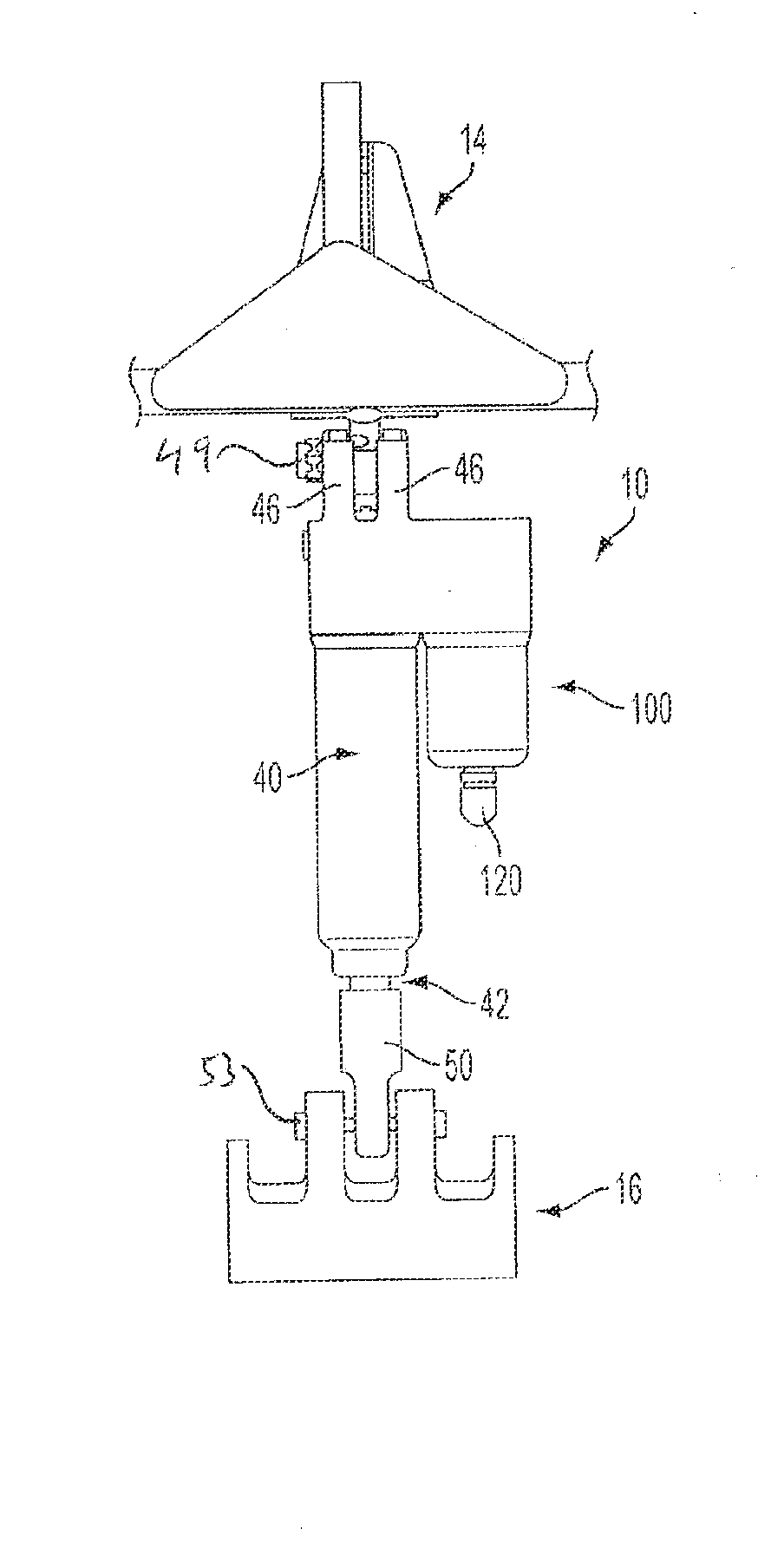
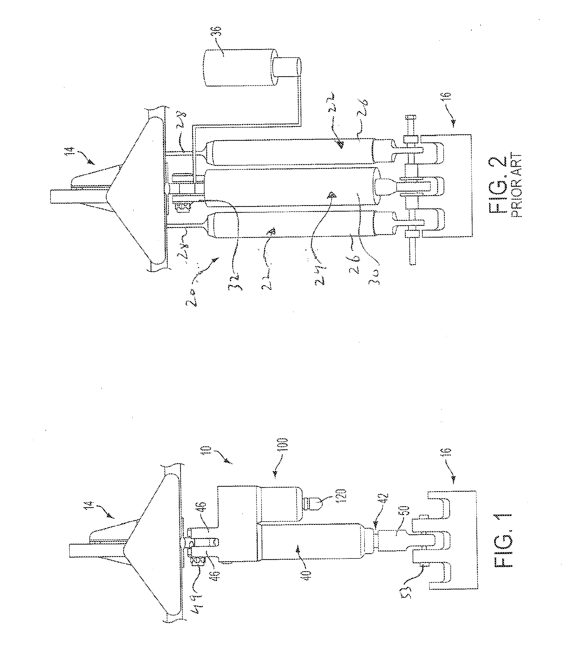
[0018]An actuator 10 in accordance with at least aspect of the present invention is shown in FIG. 1, in connection with two relatively movable parts 14, 16. It is to be appreciated that the two parts 14, 16 are only partially shown and are only schematically shown. The two parts 14, 16 may be any relatively moveable parts. Within one example, the parts 14, 16 are of a vehicle. Within one specific example, the parts 14, 16 are of an air...


PUM


Abstract

An actuator for relatively moving two parts in a damped manner. The actuator includes a damper housing for connection to a first of the parts. The damper housing includes a damper chamber. The actuator includes a drivable damper rod for connection to a second of the parts and being movable relative to the damper housing. The damper rod includes a damper unit located within the damper chamber. The damper unit is relatively movable within the damper chamber with the damper unit movement corresponding to the relative movement between the damper housing and damper rod and the relative movement between the first and second parts. The damper unit is movable in response to hydraulic pressure force upon the damper unit. The actuator includes a pneumatic pressure source for providing a pneumatic pressure force that is transferred to provide the hydraulic pressure force upon the damper unit. The actuator includes a selectively actuatable blocking device for permitting transfer of the pneumatic pressure force from the pneumatic pressure source and blocking return of force to the pneumatic pressure source until the selectively actuatable blocking device is actuated.

Description

RELATED APPLICATION[0001]Benefit is hereby claimed from U.S. Provisional Application Ser. No. 61 / 444,359, filed Feb. 18, 2011, the entire disclosure of which is hereby incorporated herein by reference.BACKGROUND OF THE INVENTION[0002]1. Field of the Invention[0003]The invention relates generally to actuators for relatively moving two elements, and specifically related to improvements in actuator technology to provide actuators that provide both a motive force with damping via the use of hydraulic and pneumatic aspects.[0004]2. Discussion of Prior Art[0005]Components for providing moving force, in assisting moving force, and / or a holding force are known. Such components are often referred to as actuators, lifters, gas springs or the like, such components are often used to move one part relative to another. In one specific example, such components are utilized for movement of a part of a vehicle. In one specific example, the part of a vehicle is a door. Often, such components are util...

Claims


Application Information

Patent Timeline
Patent Type & Authority Applications(United States)
IPC IPC(8): F15B15/00
CPCF15B15/00F16F9/56F16F9/065
Inventor FRANKLIN, III, SAMUEL JASPERTRIEBS, VOLKERGABRIEL, STEFANZUELLING, ROLANDKLEIBER, MICHAEL CHRISTOF
Owner CURTISS WRIGHT CONTROLS
Why Eureka
Try Eureka