Roller cover

Inactive Publication Date: 2014-01-02
OERLIKON SOLAR AG (TRUEBBACH)
View PDF9 Cites 2 Cited by
  • Summary
  • Abstract
  • Description
  • Claims
  • Application Information

AI Technical Summary

Benefits of technology

[0007]It is an object of the present invention to improve process performance of a substrate treatme

Problems solved by technology

Due to the movement of parts present in the deposition system, such as roller means for transporting the s

Method used


Image

  • Roller cover
  • Roller cover
  • Roller cover

Examples


Example

DETAILED DESCRIPTION OF DRAWINGS

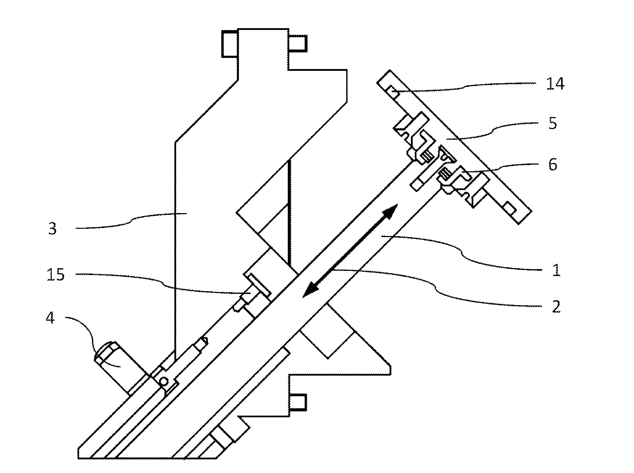
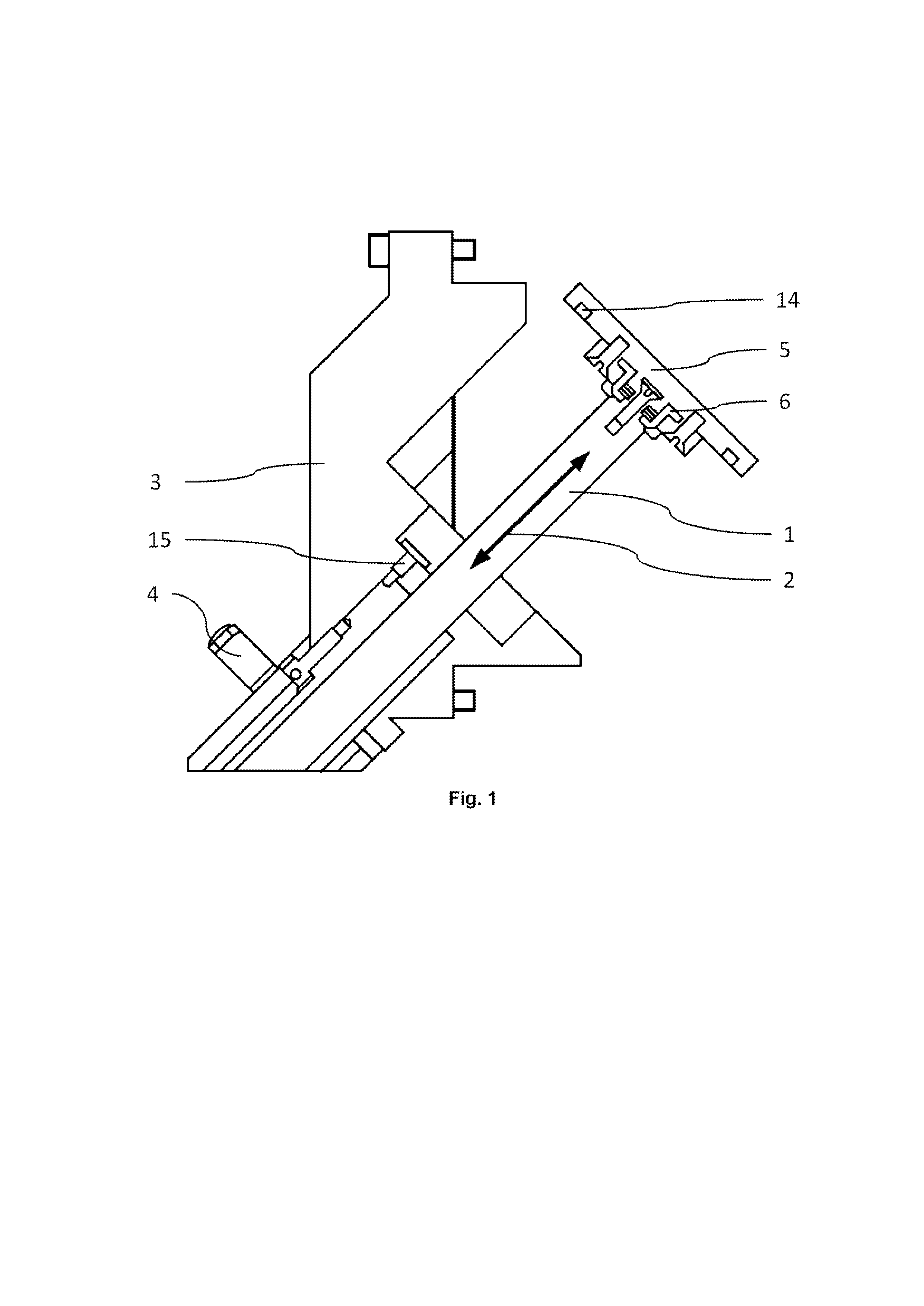
[0046]FIGS. 1 to 9 show a roller driver device for use in a deposition system for manufacturing a photovoltaic device. The roller drive device comprises a cover means 1 which is slidable along a cover means axis 2 from an opening position, shown in FIG. 1, into a shielding position, shown in FIG. 2.

[0047]The cover means is attached to a housing 3 of the roller drive device, whereby a motorized means 4 is arranged for sliding the cover means 1 between the shielding position and the opening position. Furthermore, the cover means 1 comprises a cover head 5 which is attached to the cover means 1 by a quick change means 6 for quickly removing the cover means head 5 and exchanging to another cover means head 5.

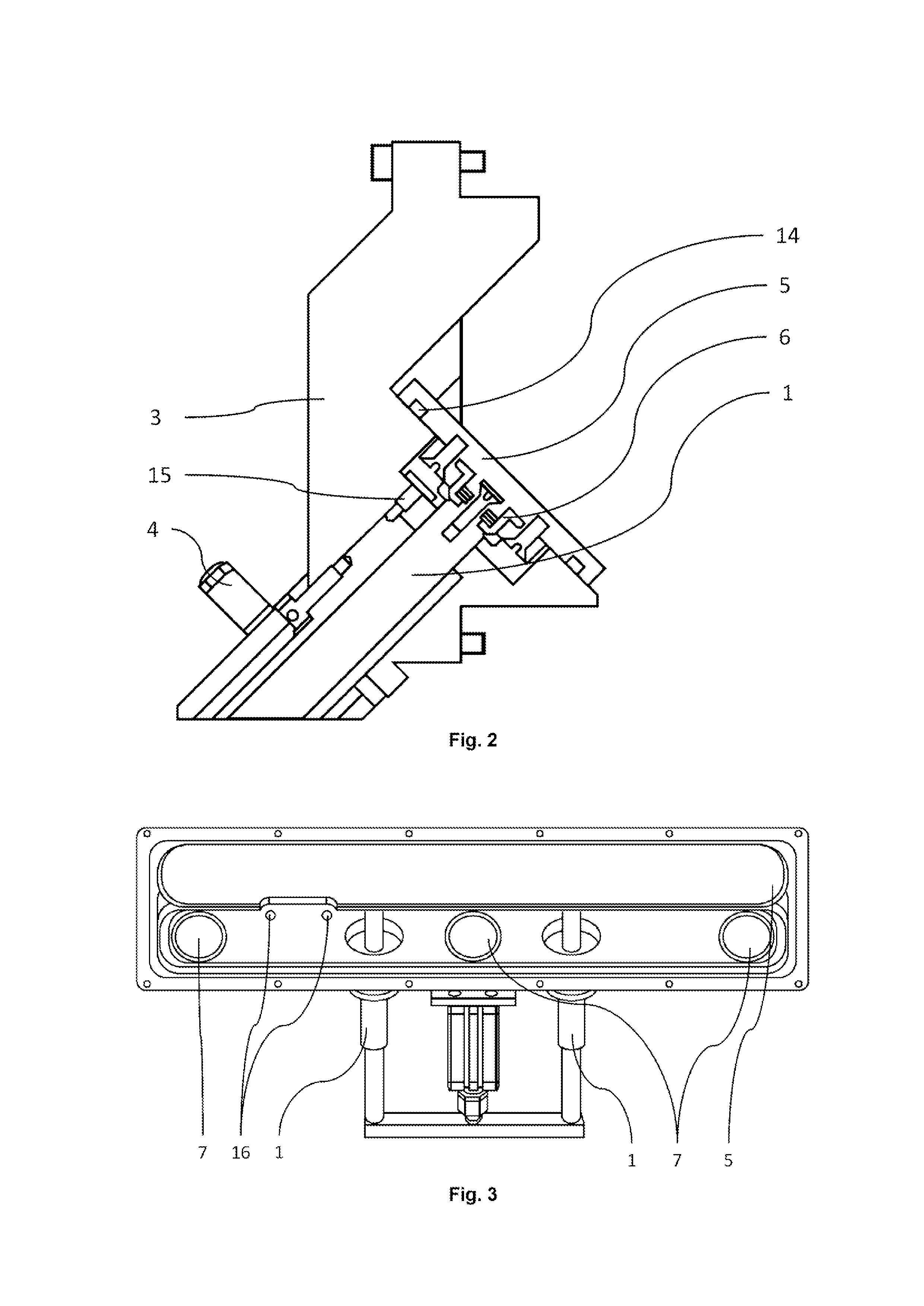
[0048]As can be seen from FIG. 3, one single cover means head 5 is connected to two cover means axes 2 having each a motorized means 4 such that the single cover head 5, if the cover means 1 is in the shielding position, protect three openings 7. The ...


PUM


Abstract

The invention relates to a roller drive device for use in a deposition system for manufacturing a photovoltaic device having a substrate (12), the roller drive device comprising a roller means (9) and a cover means (1), whereby the roller means is arranged slidable along a roller means axis (11) between a rolling position and a retracting position, whereby the roller means is configured for transporting the substrate in the rolling position, the cover means is arranged slidable along a cover means axis (2) between a shielding position and an opening position, whereby, if the roller means is in the retracting position, the cover means is configured for shielding the roller means against contamination by a substance present in the deposition system in the shielding position, and the roller means axis and the cover means axis are arranged tilted to each other.

Description

TECHNICAL FIELD[0001]The present invention relates to the field of transporting a substrate in a deposition system. Particularly, the present invention discloses a device for improving process performance of a substrate deposition system.BACKGROUND ART[0002]Photovoltaic devices, photoelectric conversion devices or solar cells are devices which convert light, especially sunlight into direct current electrical power. For low-cost mass production thin film solar cells are being of interest since they allow using glass, glass ceramics or other rigid or flexible substrates as a base material, i.e. as a substrate. The solar cell structure, i.e. the layer sequence responsible for or capable of the photovoltaic effect is being deposited in thin layers.[0003]The deposition of said layers is typically done in a CVD system. The reactants, e.g. precursor materials, are being fed into process stations by a so called gas shower. The substrate, e.g. a workpiece to be treated, e.g. coated, is being...

Claims


Application Information

Patent Timeline
IPC IPC(8): B65G13/02H01L31/18
CPCB05B13/0221H01L21/67706
Inventor CLAUSS, MICHAELJAEGER, SILVIOFORNARO, ALEXANDERCASTELMUR, GUIDORAFFAELE, LIBERATO
Owner OERLIKON SOLAR AG (TRUEBBACH)
Why Eureka
Try Eureka