
Driver

a technology of driver blade and driver blade, which is applied in the field of drivers, can solve the problems of noise and vibration, noise and vibration, and the operation of the driver described above, and achieve the effect of suppressing the vibration of the driver blade and reducing the noise of the driver blad

Inactive Publication Date: 2014-01-02
HITACHI KOKI CO LTD
View PDF0 Cites 3 Cited by
  • Summary
  • Abstract
  • Description
  • Claims
  • Application Information

AI Technical Summary

Benefits of technology

The invention aims to reduce the noise of a vehicle driver by reducing the vibration of the driver's blade. By reducing the vibration of the blade, the noise of the driver is also reduced.

Problems solved by technology

The operation of the driver described above generates the noise and vibration.
There are many sources of the noise and vibration, and one example thereof is the vibration of the driver blade.
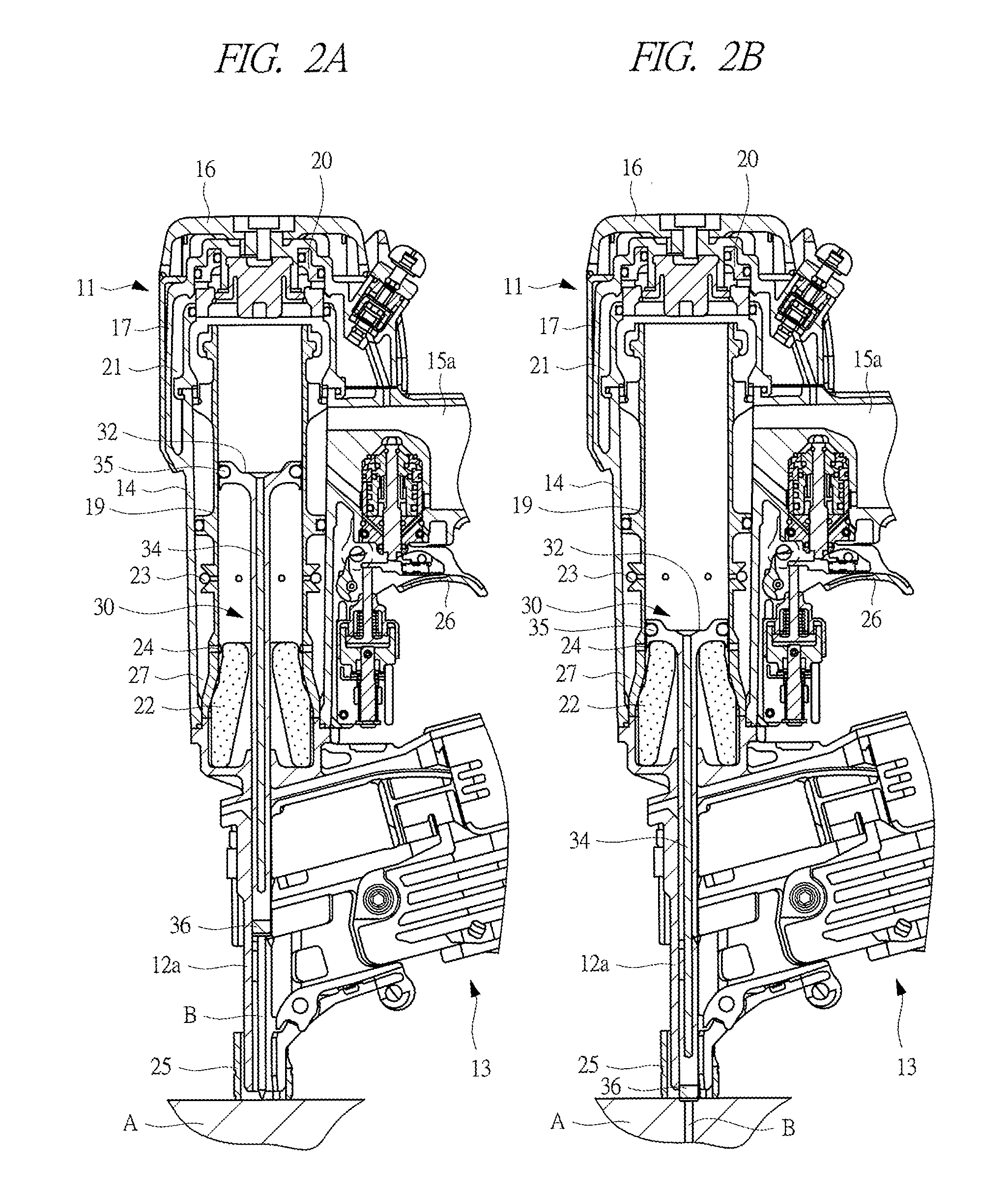
Specifically, when the driver blade strikes a head of a fastener, the driver blade vibrates due to the impact thereof, so that the noise is generated.
However, the matters described in Japanese Patent No. 3211225 relate to the reduction of noise generated at the time of exhausting the compressed air which has pushed down the driver blade (exhaust noise), and Japanese Patent No. 3211225 does not describe and suggest the vibration of the driver blade and the noise generated by the vibration.

Method used


Image

  • Driver
  • Driver
  • Driver

Examples


Embodiment Construction

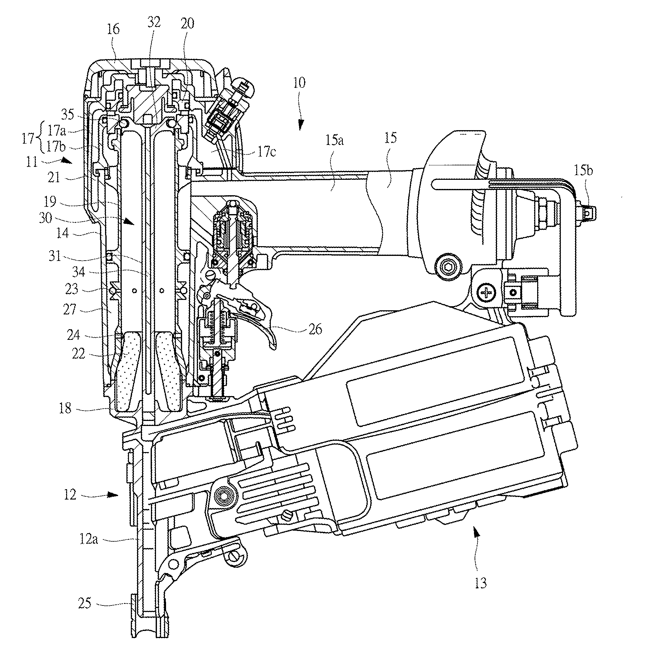
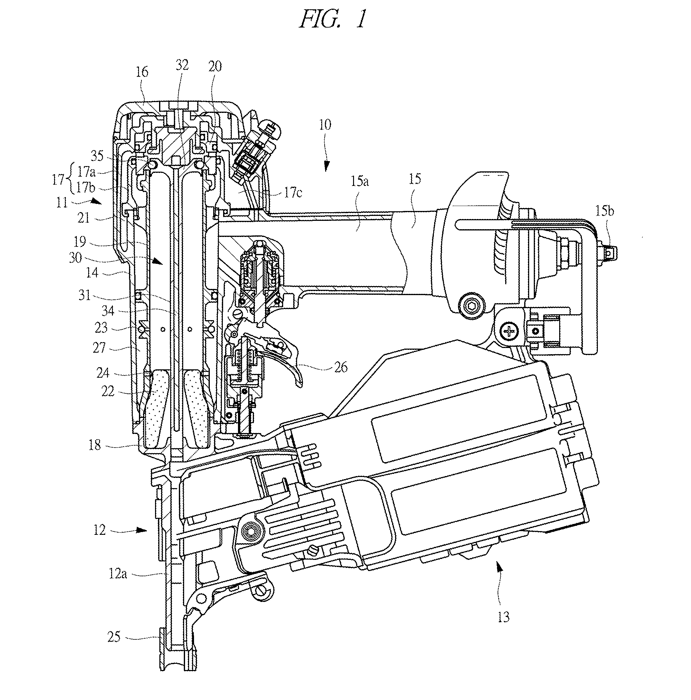
[0018]Hereinafter, embodiments of the present invention will be described in detail with reference to drawings. A driver 10 shown in FIG. 1 has a main body section 11, a driving section 12, and a magazine 13.

[0019]The main body section 11 has a housing 14, a handle 15, a head cover 16, a guide part 17, and an under cover 18. The housing has a hollow structure. The guide part 17 is provided in an opening on one end side of the housing 14, the under cover 18 is provided in an opening on the other end side, and the head cover 16 is placed on the guide part 17. A cylindrical cylinder 19 is housed in the housing 14. An upper end of the cylinder 19 protrudes through the opening on one end side of the housing 14 and enters the guide part 17.

[0020]The handle 15 is apart gripped by a worker who uses the driver 10, and a pressure accumulation chamber 15a is provided therein. One end of the handle 15 is fixed to the housing 14 and the guide part 17, and a plug 15b is provided at the other end ...


PUM


Abstract

A driver which strikes a fastener to drive it into a target object has a cylinder and a driver blade which is reciprocably housed in the cylinder and is driven to reciprocate by pressure of fluid supplied into the cylinder to strike the fastener, and the driver blade is made up of a shaft part and a piston provided at one end of the shaft part and a damping member is incorporated in the shaft part.

Description

CROSS-REFERENCE TO RELATED APPLICATION[0001]The present application claims priority from Japanese Patent Application No. 2012-146217 filed on Jun. 29, 2012, the content of which is hereby incorporated by reference into this application.TECHNICAL FIELD OF THE INVENTION[0002]The present invention relates to a driver which drives a fastener such as a nail or a screw into a target object such as a timber or a drywall.BACKGROUND OF THE INVENTION[0003]A driver which strikes a fastener with a reciprocating driver blade to drive it into a timber or a drywall has been known. Japanese Patent No. 3211225 describes a driver using compressed air as a power source of a driver blade.[0004]The driver described in Japanese Patent No. 3211225 is provided with a cylinder which contains a driver blade. The driver blade is pushed down by the pressure of the compressed air supplied to the cylinder and strikes a head of a fastener. Specifically, the driver blade is pushed down by the pressure of the compr...

Claims


Application Information

Patent Timeline
Patent Type & Authority Applications(United States)
IPC IPC(8): B25C1/04
CPCB25C1/047
Inventor ICHIKAWA, KAORUTANJI, ISAMUHIRAI, SYOUICHIKOMAZAKI, YOSHIICHI
Owner HITACHI KOKI CO LTD
Learn More