
Method and apparatus for transmitting and receiving signal

Active Publication Date: 2014-01-02
IND ACADEMIC COOP FOUNDATION YONSEI UNIV
View PDF5 Cites 0 Cited by
  • Summary
  • Abstract
  • Description
  • Claims
  • Application Information

AI Technical Summary

Benefits of technology

The present invention provides a way to improve the reception of signals in an indoor environment by minimizing inter-symbol interference caused by channels with frequency-selective characteristics. This is done by preprocessing the signals using a parameter that determines the signal to sidelobe ratio, which results in a reduction in inter-symbol interference and maintains signal strength. The preprocessed signals are then transmitted through a specific channel to a receiving apparatus. Overall, this method and apparatus improve the performance of existing systems and design an optimal filter to solve the problem of maximizing signal power while minimizing inter-symbol interference.

Problems solved by technology

The related art has used a code division multiple access scheme to solve inter-symbol interference (ISI), but has a problem in that a receiving apparatus is complicated.
In this case, a mobile communication or Bluetooth receiving apparatus using a wireless terminal has a large volume, so that the mobile communication or Bluetooth receiving apparatus is difficult to be carried and consumes a considerable amount of power, so that the receiving apparatus is difficult to use.
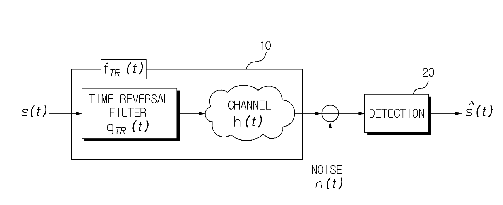
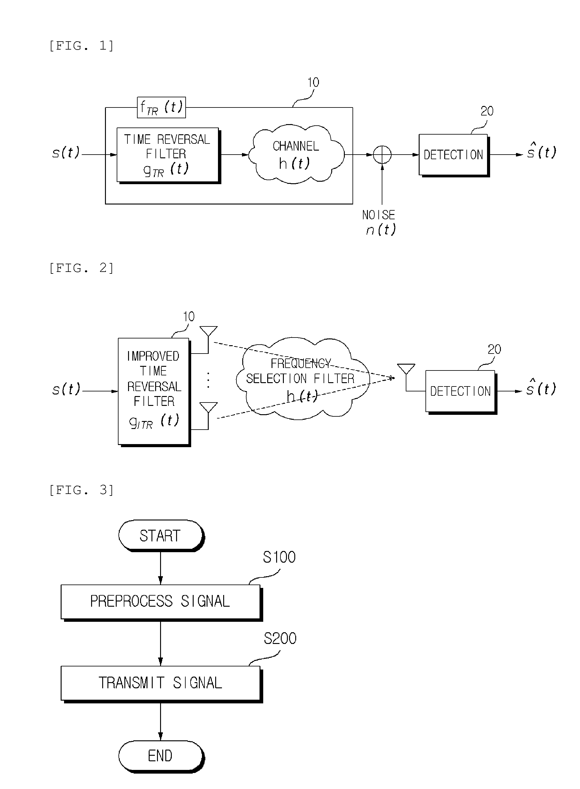
However, although a transmitting signal to noise ratio is very high, the time reversal technique cannot completely remove the MUI occurring on the spatial axis and the ISI occurring on the temporal axis, thereby causing performance degradation.
However, since the zero-forcing technique is a filter for the purpose of reducing interference, a magnitude in a main peak of a received signal becomes relatively very small.
Therefore, when the ZF technique is exposed to actually used environmental noises, performance may be degraded.
Therefore, the performance may be degraded under the situation in which the environment is poor.

Method used


Image

  • Method and apparatus for transmitting and receiving signal
  • Method and apparatus for transmitting and receiving signal
  • Method and apparatus for transmitting and receiving signal

Examples


Embodiment Construction

[0039]The following contents illustrate only a principle of the present invention. Therefore, although not clearly described or illustrated in the present specification, those skilled in the art may implement the principle of the invention and invent various apparatuses included in the concept and scope of the invention. All the conditional terms and embodiments described in the present specification are in principle used only to understand the concept of the present invention, and therefore need to be construed as not being limited to particularly described embodiments and states.

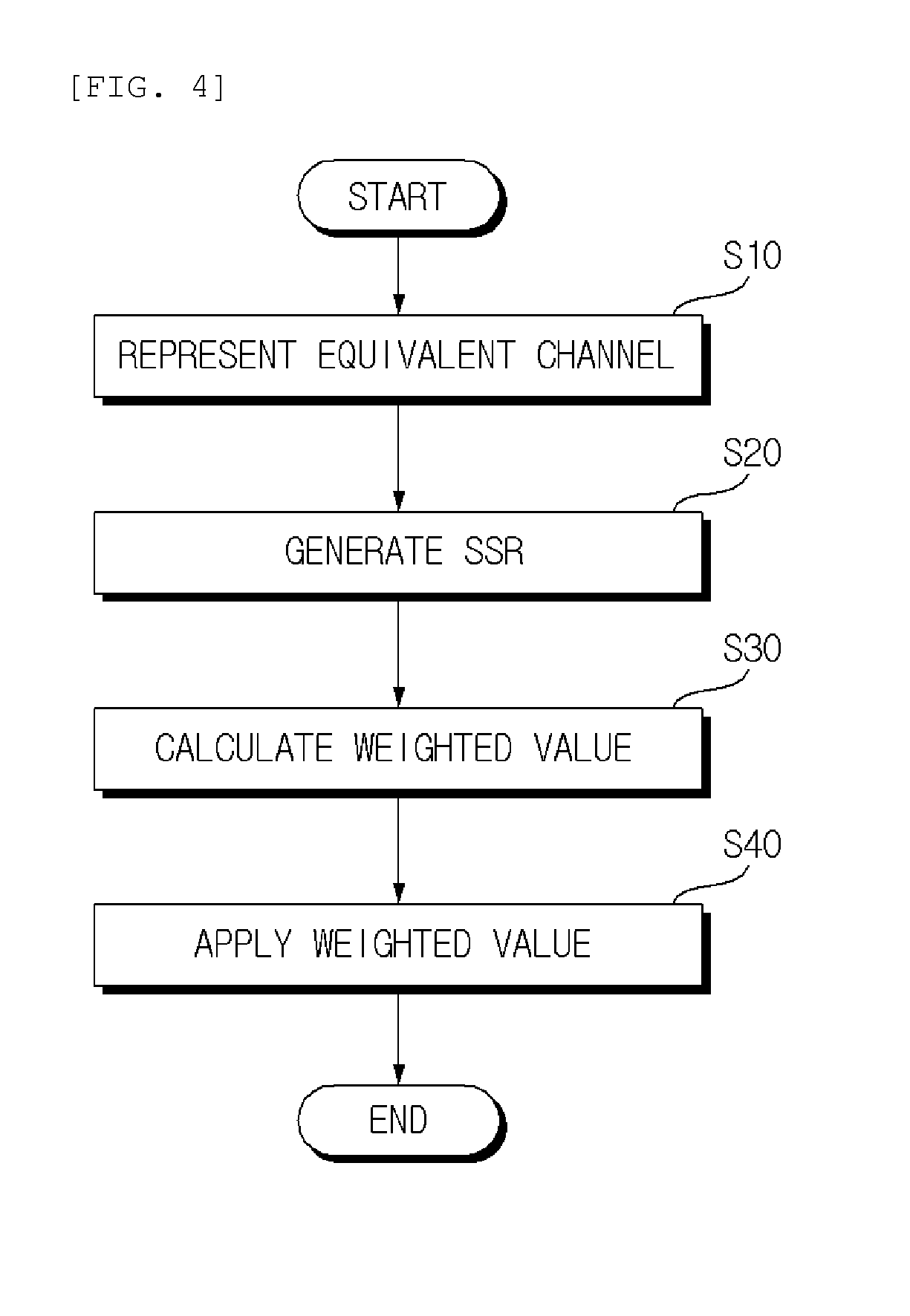
[0040]The foregoing purposes, features, and advantages will be more apparent based on the following detailed description with reference to the accompanying drawings, and therefore a person with ordinary skill in the art to which the present invention pertains can easily practice the technical idea of the present invention. In describing the present invention, when a detailed description of well-known techn...


PUM


Abstract

Provided are a method and an apparatus for transmitting a signal suitable for an indoor environment. The method for transmitting a signal according to an exemplary embodiment of the present invention includes: preprocessing a signal using a signal power to sidelobe power ratio (SSR) parameter defining a signal to sidelobe ratio to minimize an inter-symbol interference and prevent performance deterioration due to reduction in signal strength; and transmitting the preprocessed signal to a receiving apparatus through a predetermined channel.

Description

CROSS-REFERENCE TO RELATED APPLICATIONS[0001]This application claims priority to and the benefit of Korean Patent Application No. 10-2012-0071278 filed in the Korean Intellectual Property Office on Jun. 29, 2012, the entire contents of which are incorporated herein by reference.TECHNICAL FIELD[0002]The present invention relates to a method and an apparatus for transmitting and receiving a signal suitable for an indoor environment. More particularly, the present invention relates to a method and apparatus for transmitting and receiving a signal for supporting high speed data communication without performance degradation even in a channel having frequency selective characteristics by minimizing inter-symbol interference (ISI).BACKGROUND ART[0003]Since a signal is transmitted through a channel having frequency selective characteristics in an indoor environment, a delayed and received symbol serves as interference with a subsequent symbol. The related art has used a code division multip...

Claims


Application Information

Patent Timeline
IPC IPC(8): H04W52/24
CPCH04W52/24H04W52/245H04B17/336H04B7/005
Inventor LEE, CHUNG YONGYOON, MI SUN
Owner IND ACADEMIC COOP FOUNDATION YONSEI UNIV
Learn More