Tracking brain deformation during neurosurgery

a brain deformation and neurosurgery technology, applied in the field of brain deformation determination, can solve problems such as local brain deformation, and achieve the effect of accurately estimating local brain deformation

Active Publication Date: 2014-01-02
KONINKLIJKE PHILIPS ELECTRONICS NV
View PDF10 Cites 4 Cited by
  • Summary
  • Abstract
  • Description
  • Claims
  • Application Information

AI Technical Summary

Benefits of technology

[0019]It can be seen as the gist of the invention to provide an elastic three-dimensional registration in order to achieve the local displacements of the current brain structure. The elastic registration is performed for the vessel structure or vasculature. The determined deformation of the vessel is then applied to the brain structure itself. In other words, the present invention provides performing the elastic registration for the vessel structure first, and not directly for the brain structure. The determined deformation is then applied, or transformed, to the brain itself, because the vessels in the brain are contained within the convolutions, and because local displacements of vessels in the brain allow for accurately estimating the local brain deformation. The brain deformation may then be used to adjust pre-procedural planning to the actual current situation. The brain deformation information may also be fed into an external navigation system, for example for steering an interventional device. The image data for the 3D representation, in particular for the second representation are provided with contactless image acquisition, for example with X-ray imaging and thus do not affect the brain deformation itself.

Problems solved by technology

However, during neurosurgery, for example during neuro-operations or neuro-interventions, for example, the leakage of the cerebral spinal fluid can result in a local deformation of the brain during treatment.

Method used


Image

  • Tracking brain deformation during neurosurgery
  • Tracking brain deformation during neurosurgery
  • Tracking brain deformation during neurosurgery

Examples


Embodiment Construction

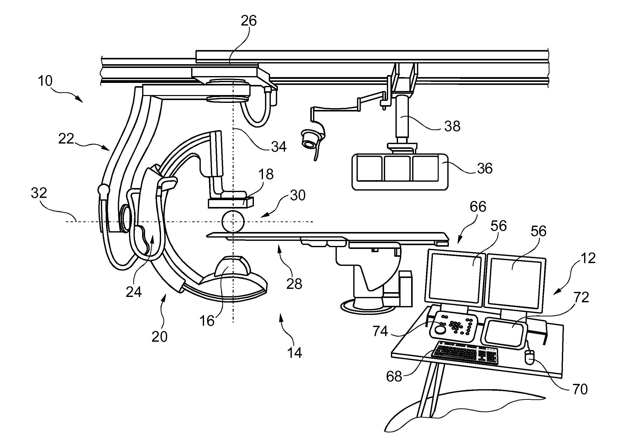
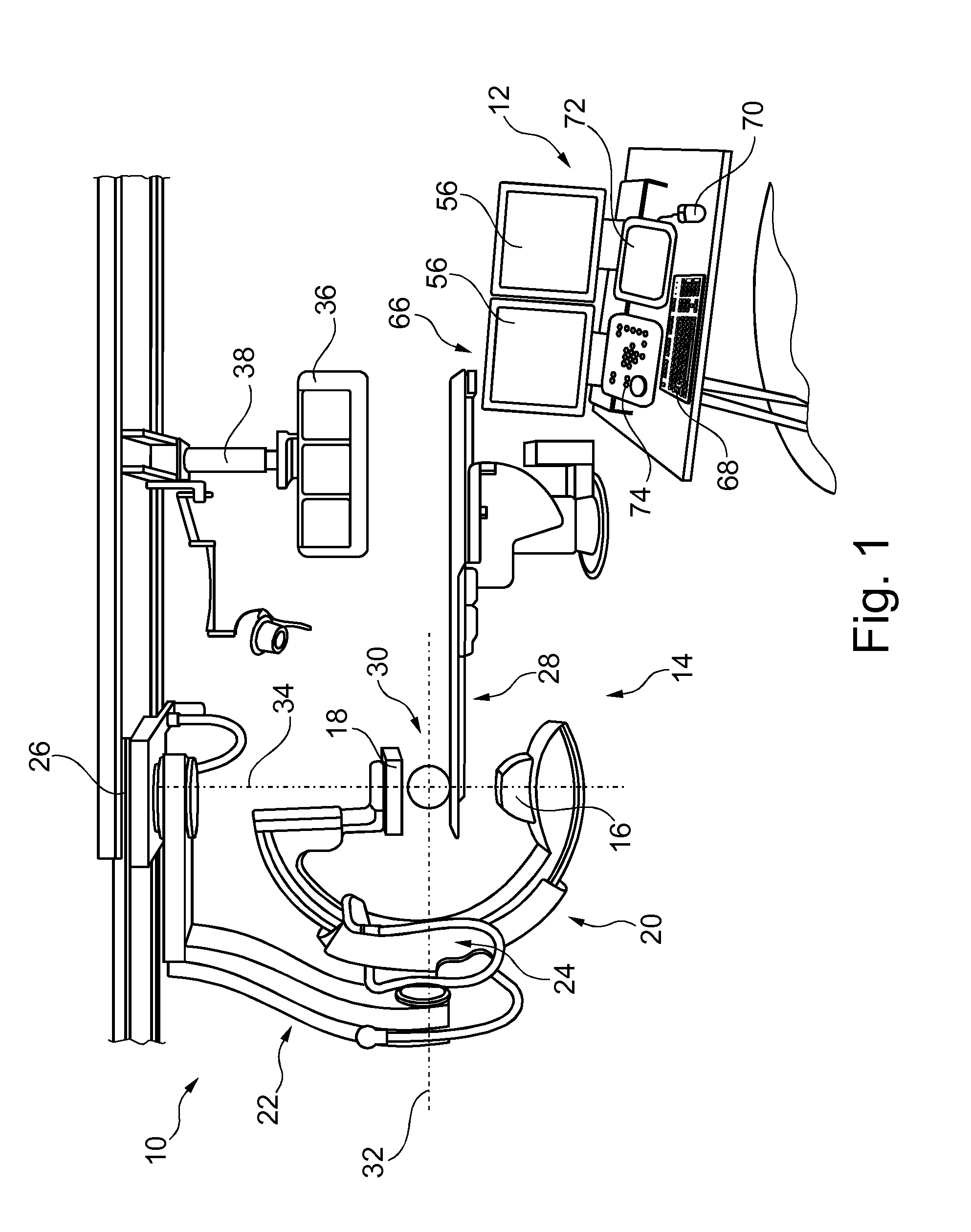
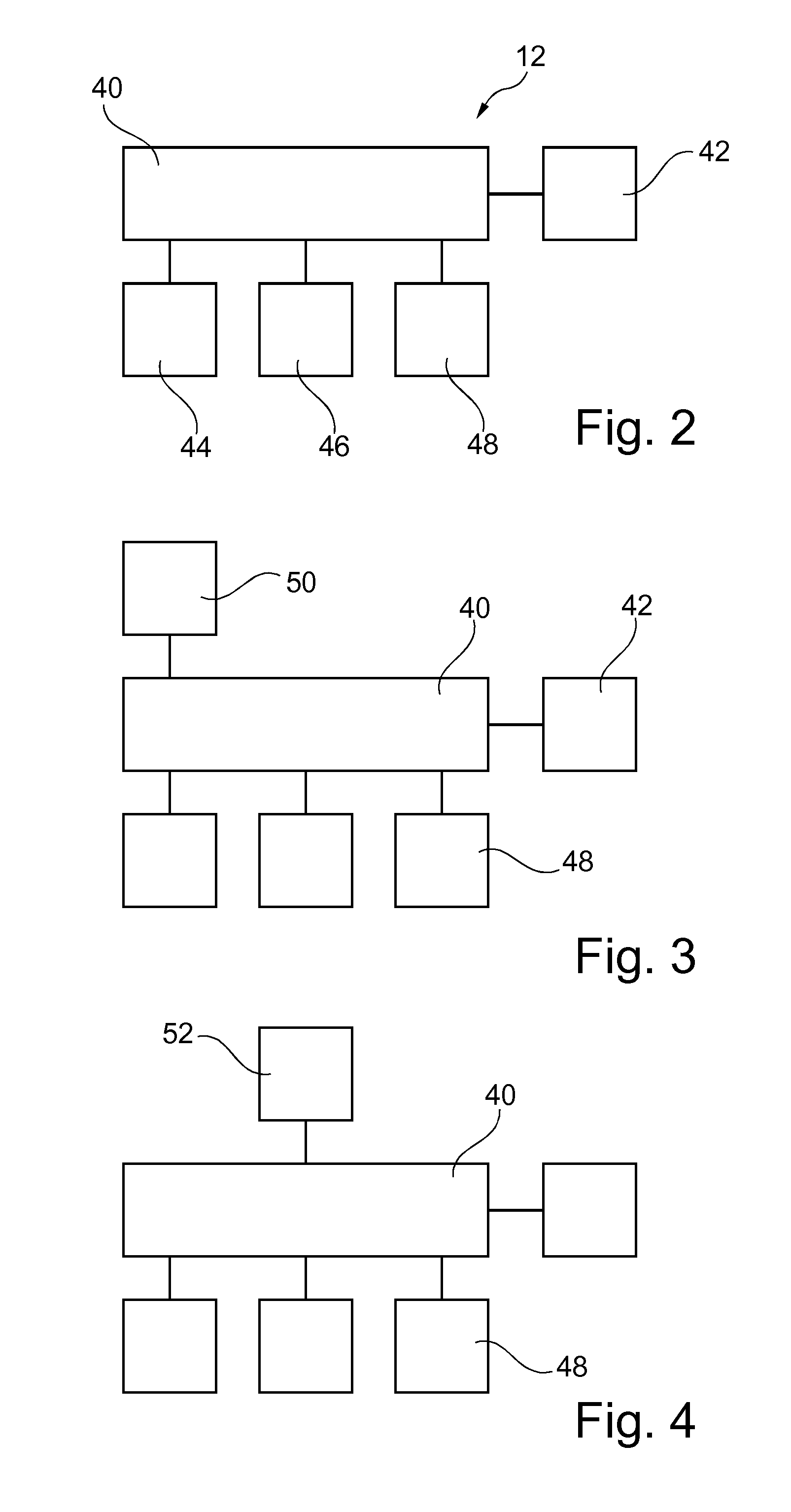
[0029]FIG. 1 schematically illustrates an imaging system 10 for tracking brain deformation. The system 10 comprises a device 12 for tracking brain deformation and an image acquisition device 14. The device 12 for tracking brain deformation will be explained in more detail with reference to FIGS. 2 to 9.

[0030]For example, the image acquisition device is an X-ray image acquisition device adapted to acquire 3D X-ray image data.

[0031]According to a further embodiment, not shown, the image acquisition device is an MR image acquisition device adapted to acquire 3D MR image data.

[0032]The X-ray image acquisition device 14 comprises an X-ray source 16 and a detector 18. The detector 18 and the X-ray source 16 are arranged on opposing ends of a C-arm structure 20. The C-arm structure 20 is mounted to a suspending structure 22 with a rotatable and slideable attachment 24. The suspending structure 22 is mounted to a support structure 26, for example attached to a ceiling of an operational room...


PUM


Abstract

The present invention relates to the determination of brain deformation. The invention relates in particular to a device for tracking brain deformation, an imaging system for tracking brain deformation, a method for tracking brain deformation, a method of operating a device for tracking brain deformation, as well as to a computer program element and a computer readable medium. For providing enhanced information about the brain deformation, a first 3D representation (112) of a cerebrovascular vessel structure of a region of interest of an object is provided (110) and (114) a second 3D representation (116) of the cerebrovascular vessel structure. Then, at least a part of the first 3D representation is elastically three dimensionally registered (118) with at least a part of the second 3D representation. A deformation field (122) of the cerebrovascular vessel structure is determined (120) based on the elastic registration. The determined vessel deformation is applied (124) to a brain structure representation to determine a deformation (126) of the cerebral structure. For example, planning data (130) for an intervention of the cerebral structure is provided (132) and the determined deformation of the cerebral structure is applied (134) to the planning data to generate deformation adjusted planning data (136).

Description

FIELD OF THE INVENTION[0001]The present invention relates to the determination of brain deformation. The invention relates in particular to a device for tracking brain deformation, an imaging system for tracking brain deformation, a method for tracking brain deformation, a method of operating a device for tracking brain deformation, as well as to a computer program element and a computer readable medium.BACKGROUND OF THE INVENTION[0002]For neurological interventions, image information is provided to a user about a region of interest. For example, U.S. Pat. No. 5,954,648 describes that images which have been collected earlier are shown to the surgeon during an operation. However, during neurosurgery, for example during neuro-operations or neuro-interventions, for example, the leakage of the cerebral spinal fluid can result in a local deformation of the brain during treatment. As a consequence, image data acquired before the treatment may be at least in local misalignment with the cur...

Claims


Application Information

Patent Timeline
Patent Type & Authority Applications(United States)
IPC IPC(8): A61B6/00
CPCA61B6/501A61B6/5217A61B6/461A61B6/467A61B6/5235A61B6/5247G06T2207/10072G06T2207/30016G06T2207/30101G06T7/33
Inventor RUIJTERS, DANIEL SIMON ANNABABIC, DRAZENKO
Owner KONINKLIJKE PHILIPS ELECTRONICS NV
Why Eureka
Try Eureka