Sensor assembly for use in medical position and orientation tracking

a technology for positioning and orientation tracking, applied in the field of sensors, can solve the problem that the contact pad is not suitable for receiving a soldered connection

Active Publication Date: 2014-01-02
STRYKER EURO OPERATIONS HLDG LLC
View PDF7 Cites 15 Cited by
  • Summary
  • Abstract
  • Description
  • Claims
  • Application Information

AI Technical Summary

Problems solved by technology

The contact pad is not suitable for receiving a soldered connection.

Method used


Image

  • Sensor assembly for use in medical position and orientation tracking
  • Sensor assembly for use in medical position and orientation tracking
  • Sensor assembly for use in medical position and orientation tracking

Examples


Embodiment Construction

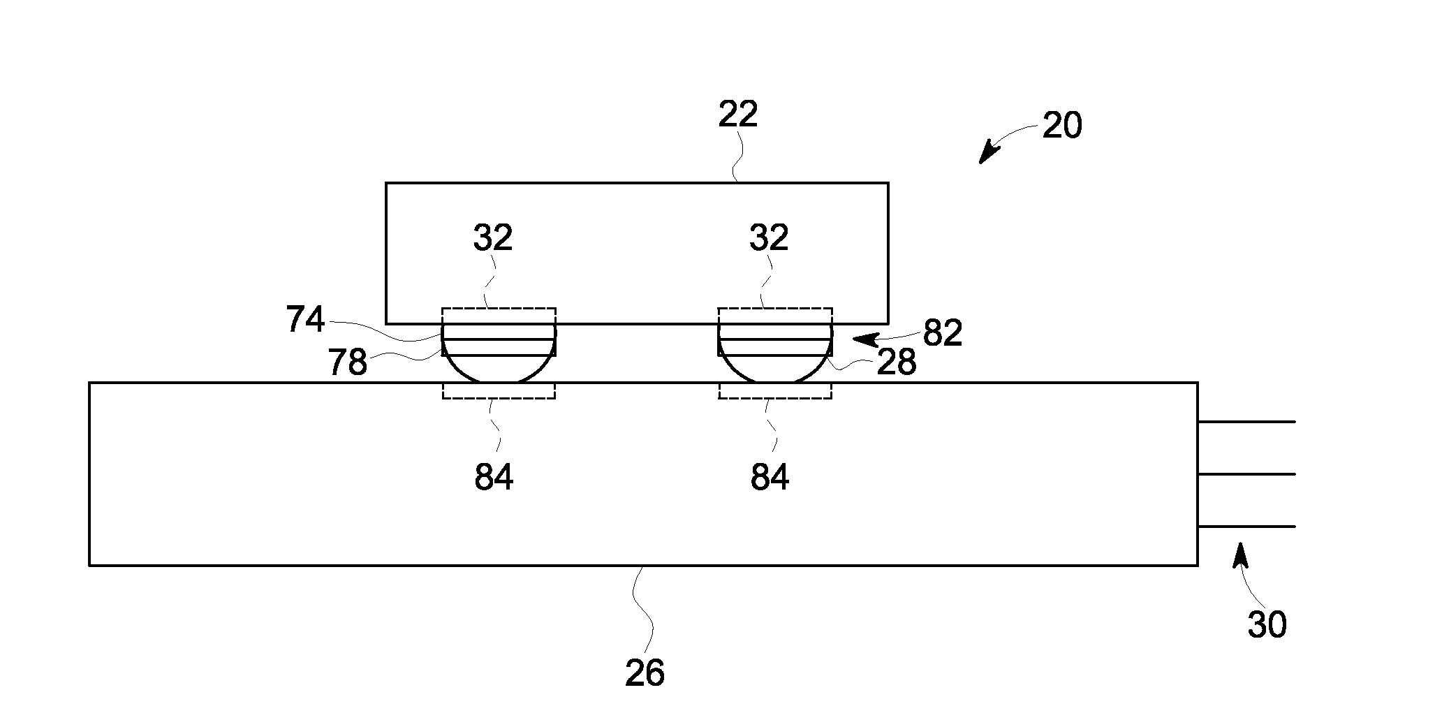
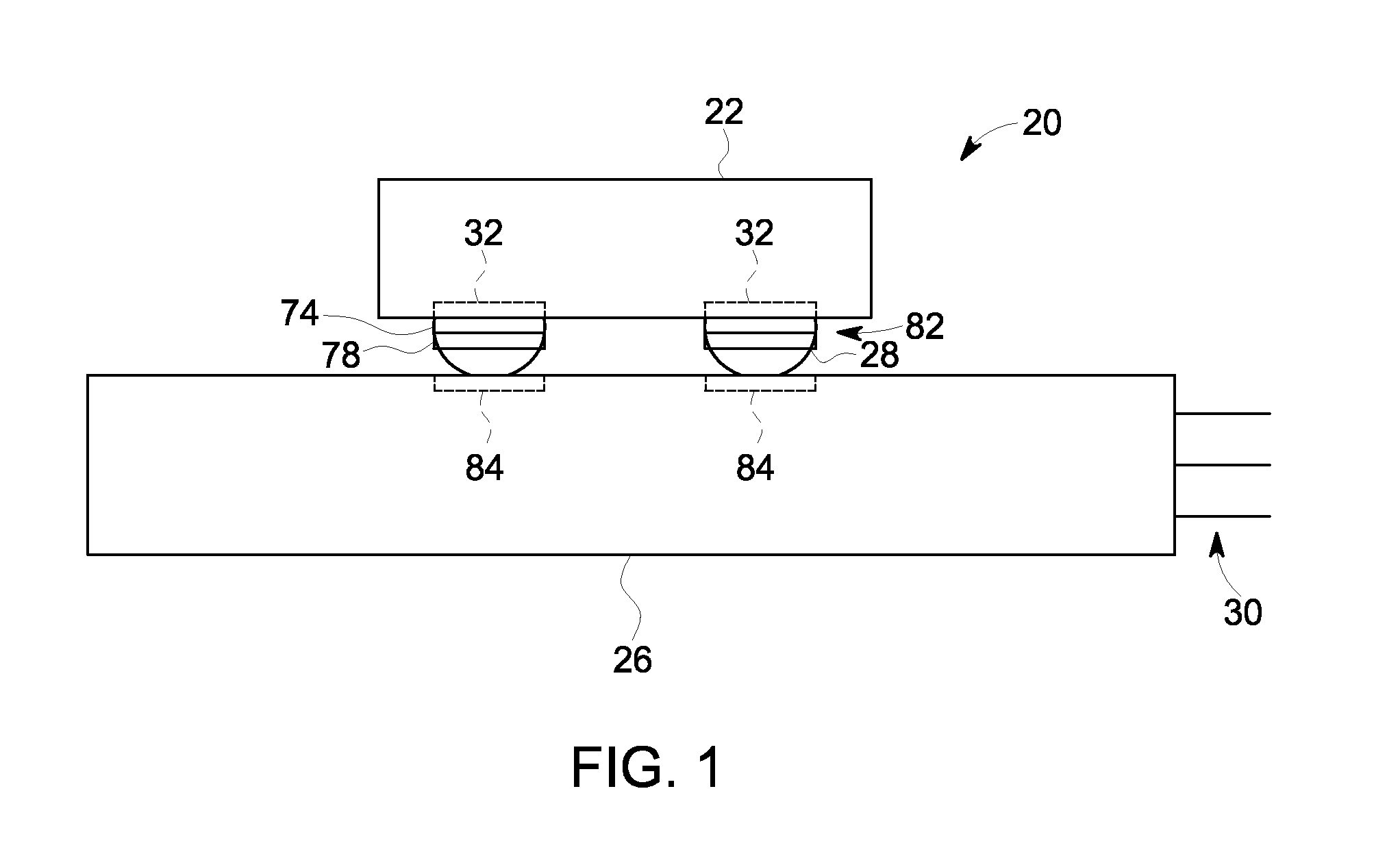
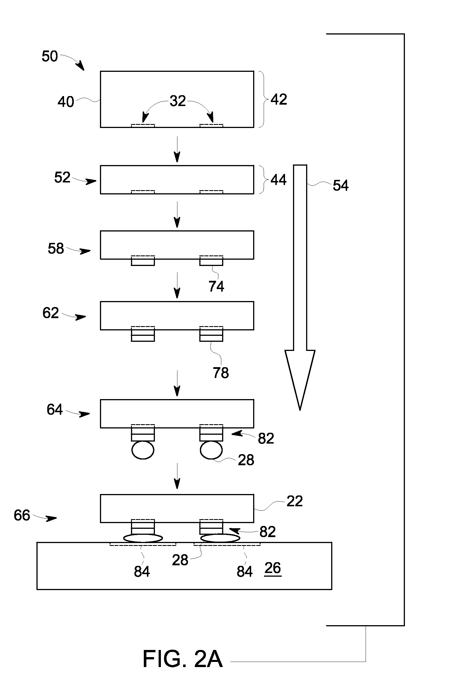
[0019]As discussed herein, a position and orientation sensor assembly is discussed that is suitable for use in a medical device, implant or instrument. In certain embodiments, the sensor assembly may include a magnetoresistance sensor, such as a two-axis electromagnetic sensor, providing six-degrees of freedom. In implementations where the position and orientation sensor is originally configured for wire bonding to an interposer that is subsequently soldered to a printed circuit board, contact pads on the sensor may be unsuitable for a soldered connection. The position and orientation sensor may, therefore, be modified by the application of various additional metallization layers so that the sensor may be interconnected directly to a substrate using an approach better suited for achieving a small form factor for the finished sensor assembly, such as a flip chip approach. For example, in implementations where the original position and orientation sensor has interconnect pads that are...


PUM


Abstract

A sensor assembly is provided for use in tracking a medical device. The sensor assembly comprises a magnetoresistance sensor capable of providing position and orientation information. In certain implementations, the magnetoresistance position and orientation sensor is originally configured for connection to a substrate using one type of interconnect approach but is modified to be connected using a different interconnect approach.

Description

BACKGROUND[0001]The subject matter disclosed herein relates generally to sensors that may be used to provide position and orientation information for an instrument, implant or device used in a medical context, such as in a surgical or interventional context. In particular, the subject matter relates to a sensor assembly sized to fit within a medical instrument, implant or device.[0002]In various medical contexts it may be desirable to acquire position and / or orientation information for a medical instrument, implant or device that is navigated or positioned (externally or internally) relative to a patient. For example, in surgical and / or interventional contexts, it may be useful to acquire position and / or orientation information for a medical device, or portion of a medical device, even when the device or relevant portion is otherwise out of view, such as within a patient's body. Likewise, in certain procedures where an imaging technique is used to observe all or part of the position...

Claims


Application Information

Patent Timeline
Patent Type & Authority Applications(United States)
IPC IPC(8): A61B5/05G01R33/09G01B7/14
CPCA61B5/062A61B2562/0223A61B2562/046G01R33/0035G01R33/0094G01R33/093H01L2224/1624Y10T428/12528
Inventor NAGARKAR, KAUSTUBH RAVINDRAHUBER, WILLIAM HULLINGERGROSZMANN, DANIEL EDUARDO
Owner STRYKER EURO OPERATIONS HLDG LLC
Why Eureka
Try Eureka