Rdma-ssd dual-port unified memory and network controller

a network controller and unified memory technology, applied in the field of network storage systems, can solve the problems of serial interfaces that need high power consumption and generate substantial heat, flash memory tends to wear out after, and achieve high input/output operations per second, high density storage capacity, and low latency

Active Publication Date: 2015-09-10
FUTUREWEI TECH INC
View PDF23 Cites 141 Cited by
  • Summary
  • Abstract
  • Description
  • Claims
  • Application Information

AI Technical Summary

Benefits of technology

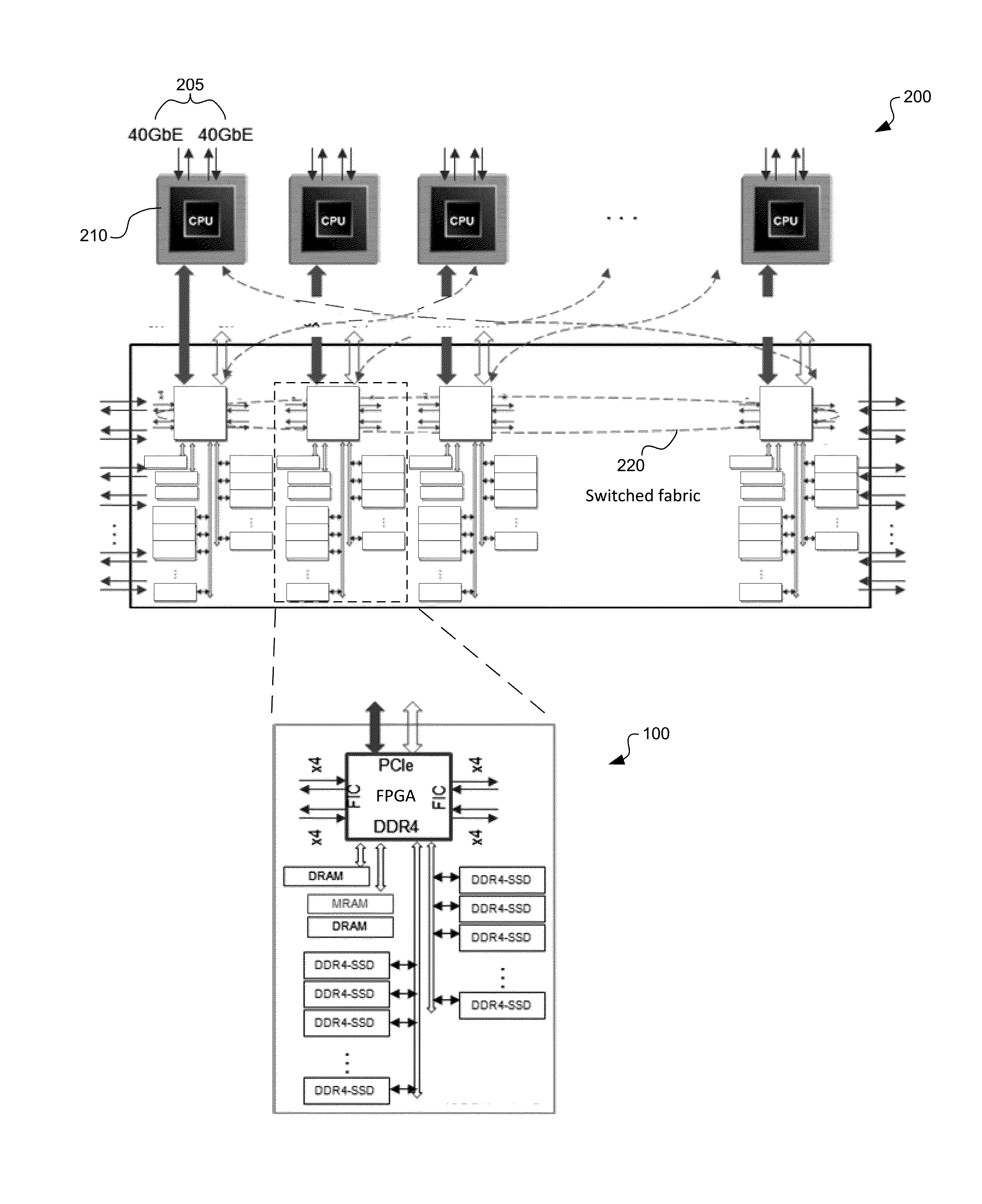
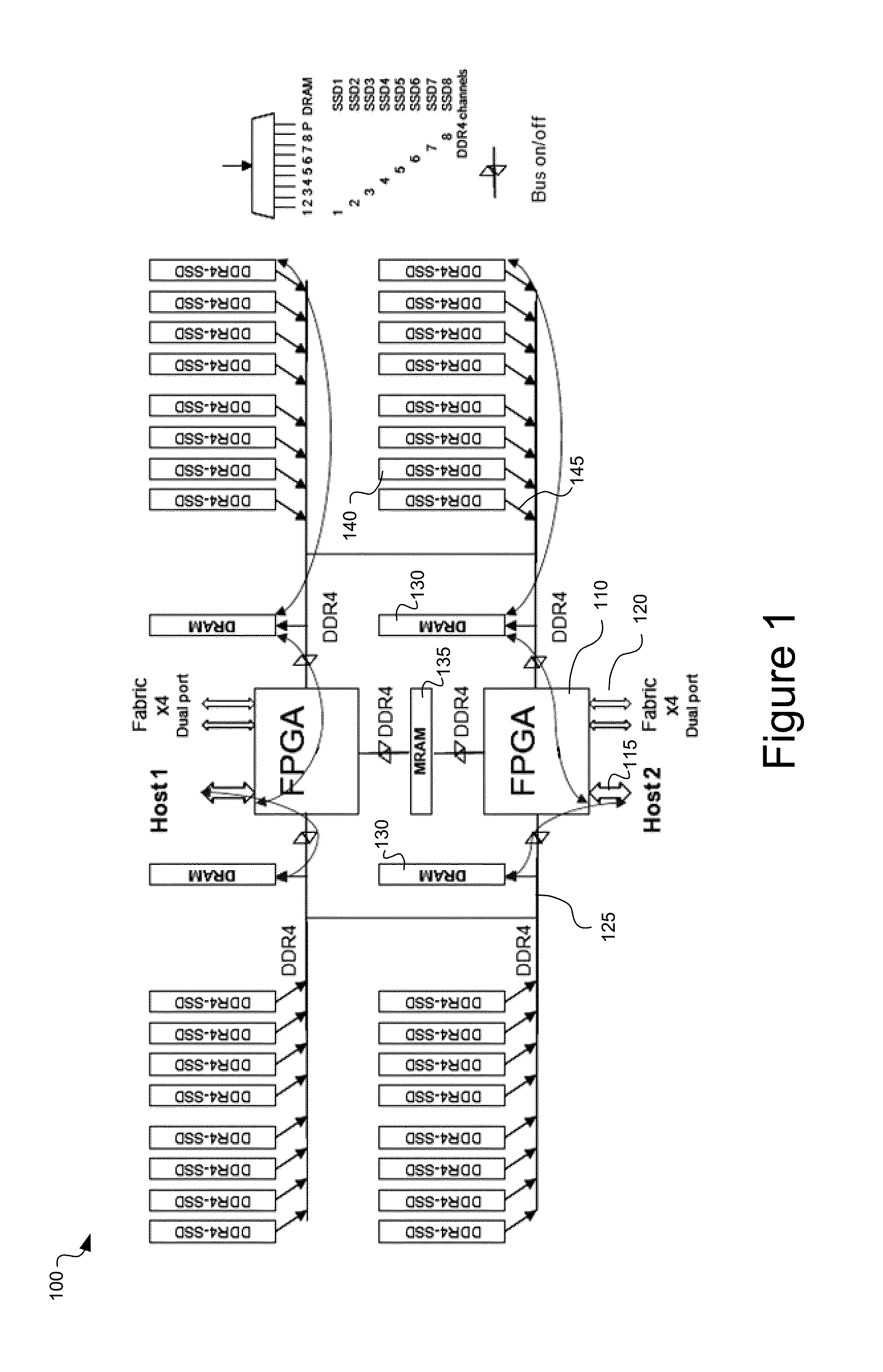
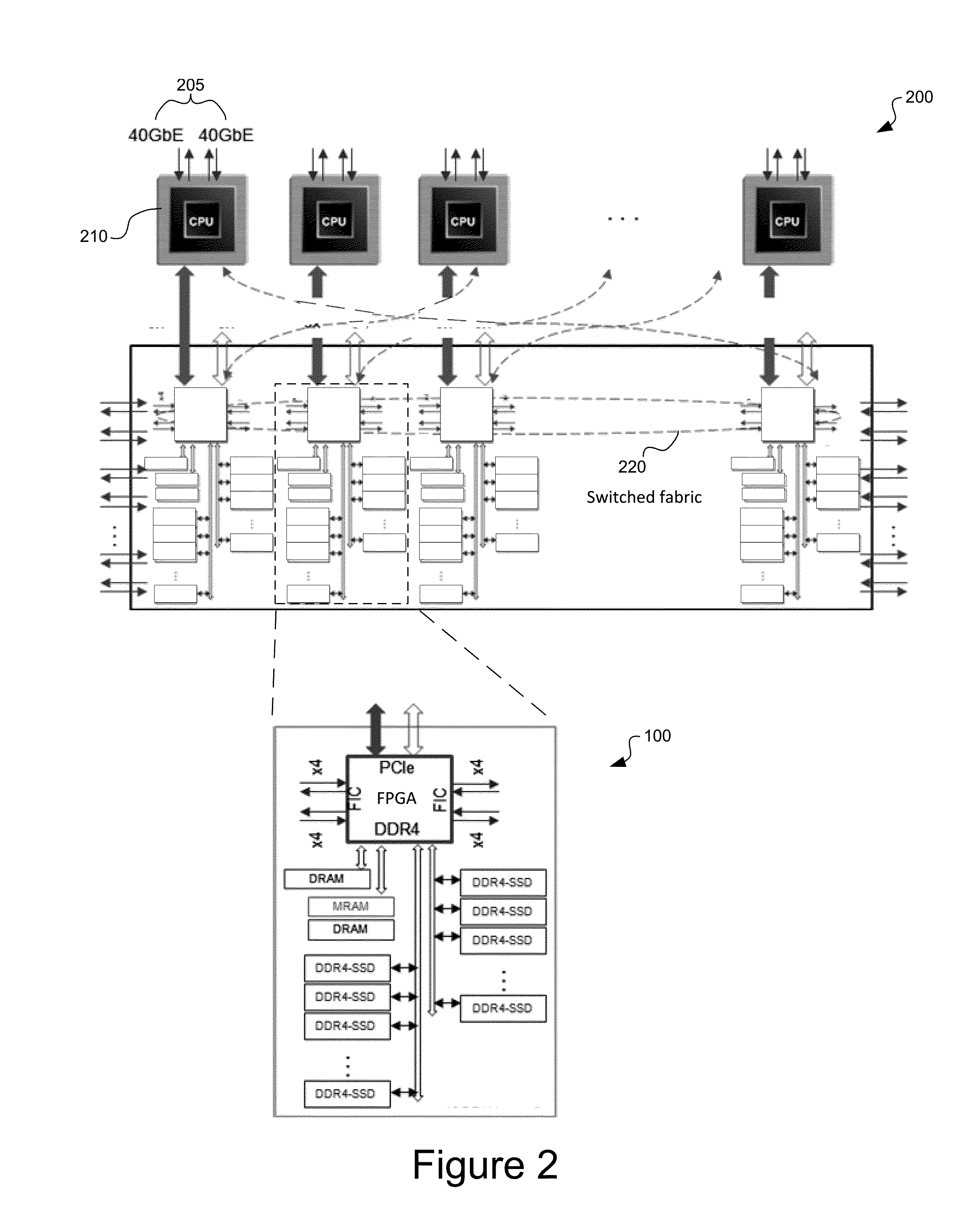
[0007]A storage network architecture including remote direct memory access-solid state drive (RDMA-SSD) clusters on a blade, having cross-over connections linking multiple RDMA-SSD blades and / or chassis for high-density storage capacity, low latency, high input / output operations per second (IOPs), high reliability and high availability, and on-demand caching resource management. Embodiments provide straightforward RDMA-device access to the cache buffers and DDR4-SSD DIMM clusters from remote client host processors and virtual machines, based on slave-memory virtualization of data buffers (e.g., DDR4-DRAMs) and DDR4-SSD DIMMs clusters on the blades and chassis across the fabric network. Low-latency zero-copy network data transfers are enabled by distributed RDMA-engines at each blade under the gateway controls, without the gateway host memory hopping necessary in conventional SSD-storage server solutions.

Problems solved by technology

However, conventional approaches to using flash memory in SATA / SAS-SSD, PCIE-SSD and / or NVME-SSD form-factors all have certain characteristics related to treatment as periphery devices that make their use in enterprise storage systems problematic.
Those serial interfaces usually need high power consumption and generate substantial heat, even as the attached periphery devices in idle states.
Furthermore, flash memory tends to wear out after a finite number of erase operations.

Method used


Image

  • Rdma-ssd dual-port unified memory and network controller
  • Rdma-ssd dual-port unified memory and network controller
  • Rdma-ssd dual-port unified memory and network controller

Examples


Embodiment Construction

[0020]Reference will now be made in detail to the various embodiments of the present disclosure, examples of which are illustrated in the accompanying drawings. While described in conjunction with these embodiments, it will be understood that they are not intended to limit the disclosure to these embodiments. On the contrary, the disclosure is intended to cover alternatives, modifications and equivalents, which may be included within the spirit and scope of the disclosure as defined by the appended claims. Furthermore, in the following detailed description of the present disclosure, numerous specific details are set forth in order to provide a thorough understanding of the present disclosure. However, it will be understood that the present disclosure may be practiced without these specific details. In other instances, well-known methods, procedures, components, and circuits have not been described in detail so as not to unnecessarily obscure aspects of the present disclosure.

[0021]S...


PUM


Abstract

System and method for a unified memory and network controller for an all-flash array (AFA) storage blade in a distributed flash storage clusters over a fabric network. The unified memory and network controller has 3-way control functions including unified memory buses to cache memories and DDR4-AFA controllers, a dual-port PCIE interconnection to two host processors of gateway clusters, and four switch fabric ports for interconnections with peer controllers (e.g., AFA blades and/or chassis) in the distributed flash storage network. The AFA storage blade includes dynamic random-access memory (DRAM) and magnetoresistive random-access memory (MRAM) configured as data read/write cache buffers, and flash memory DIMM devices as primary storage. Remote data memory access (RDMA) for clients via the data caching buffers is enabled and controlled by the host processor interconnection(s), the switch fabric ports, and a unified memory bus from the unified controller to the data buffer and the flash SSDs.

Description

CROSS-REFERENCE TO RELATED APPLICATIONS[0001]This application claims priority from U.S. Provisional Patent Application Ser. No. 61 / 950,660, filed Mar. 10, 2014 to Lee et al., entitled “RDMA-SSD CLUSTERS ON-BLADES & DDR4-SSD HD-DIMM PRIMARY STORAGES,” and is related to co-pending U.S. Utility Patent Application entitled “DDR4-SSD DUAL-PORT DIMM DEVICE,” filed on Mar. 9, 2015, which claims priority to U.S. Provisional Patent Application Ser. No. 61 / 950,708, filed Mar. 10, 2014 to Lee, entitled “DDR4-SSD DUAL-PORT DIMM BY HIGH-DENSITY FLEXIBLE-PACK DDR4-NVDIMM AS SSD LOW-LATENCY PRIMARY STORAGE.” All of these references are incorporated herein by reference.FIELD OF THE INVENTION[0002]The present disclosure pertains to network storage systems, and more particularly, to the use of remote direct memory access (RDMA) to access dynamic random access cache buffers and non-volatile solid-state memory in a network storage system of distributed all flash array (D-AFA).BACKGROUND OF THE INVENTIO...

Claims


Application Information

Patent Timeline
Patent Type & Authority Applications(United States)
IPC IPC(8): G06F3/06G11C7/10G11C14/00G06F15/173
CPCG06F3/0611G06F15/17331G06F3/0655G11C7/1072G11C14/0036G06F3/0688G06F2212/174H04L67/1097G06F12/0246G06F12/0868G06F2212/1024G06F2212/263G06F2212/7208G06F13/382G06F13/4009G11C13/0002G11C14/0018G11C14/0045
Inventor LEE, XIAOBINGYOUNG, MICHAELTING, LIYANSONG, WANGCHEN, YONG
Owner FUTUREWEI TECH INC
Why Eureka
Try Eureka