Well logging system for determining directional resistivity using multiple transmitter-receiver groups focused with magnetic reluctance material

a directional resistivity and well logging technology, applied in the field of formation properties measurement, can solve the problems of low conductivity mud system such as oil based mud, prior art ewp system limited to operating frequencies of about 200 khz or greater, phase and amplitude differences are relatively small, and are difficult to measure accurately. , to achieve the effect of increasing antenna efficiency, increasing antenna efficiency, and increasing gain

Inactive Publication Date: 2003-06-10
WEATHERFORD TECH HLDG LLC
View PDF10 Cites 142 Cited by
  • Summary
  • Abstract
  • Description
  • Claims
  • Application Information

AI Technical Summary

Benefits of technology

Each transmitter and receiver element comprises a plurality of axial slots fabricated within the wall of the tubular pressure housing member of the tool. Alternately, the transmitter and receiver elements can be fabricated as separate units and subsequently integrated into the housing member. Each slot is defined by adjacent lands with an outer radius essentially equal to the outer radius of the tool housing, and a surface of lesser radius. An essentially circular antenna, in a plane perpendicular to the axis of the tubular housing member, traverses each slot and traverses each land through a radial antenna pathway therein. Magnetic reluctance material such as ferrite is positioned within the slots on the surface of lesser radius. This increases antenna efficiency by increasing gain for a given power level. In an alternate embodiment of the invention, the antenna pathways of the low frequency transmitters and receivers are coated with highly conducting material to increase antenna efficiency. In yet another embodiment, the interiors of the slots are also coated with the highly conducting material still further increasing antenna efficiency.
By using an operating frequency of 100 kHz or lower along with higher operating frequencies, and by using the previously discussed transmitter-receiver group spacings, depth of investigation of the tool is greater than any known prior art EWP resistivity logging system. This increased depth of investigation is advantageous in obtaining true formation resistivity in highly invaded formations. The increased depth of investigation is also advantageous when the tool is embodied as a geosteering system which measures the distance between the tool and adjacent formations of contrasting resistivity.

Problems solved by technology

Since the mud must be conductive, these systems will not operate in low conductivity mud systems such as oil based muds.
Prior art EWP systems have, however, been limited to operating frequencies of about 200 kHz or greater.
At operating frequencies around 100 kHz, however, phase and amplitude differences are relatively small and difficult to measure accurately.
In anisotropic or dipping-bed formations, measurements from such systems alone do not have all the information necessary to uniquely determine horizontal and vertical resistivities as well as the dip angle.
Prior art resistivity logging systems using transmitter and receiver antenna lying in planes perpendicular to the axis of the logging tool are, as a group, not suited for azimuthal resistivity measurements.

Method used


Image

  • Well logging system for determining directional resistivity using multiple transmitter-receiver groups focused with magnetic reluctance material
  • Well logging system for determining directional resistivity using multiple transmitter-receiver groups focused with magnetic reluctance material
  • Well logging system for determining directional resistivity using multiple transmitter-receiver groups focused with magnetic reluctance material

Examples


Embodiment Construction

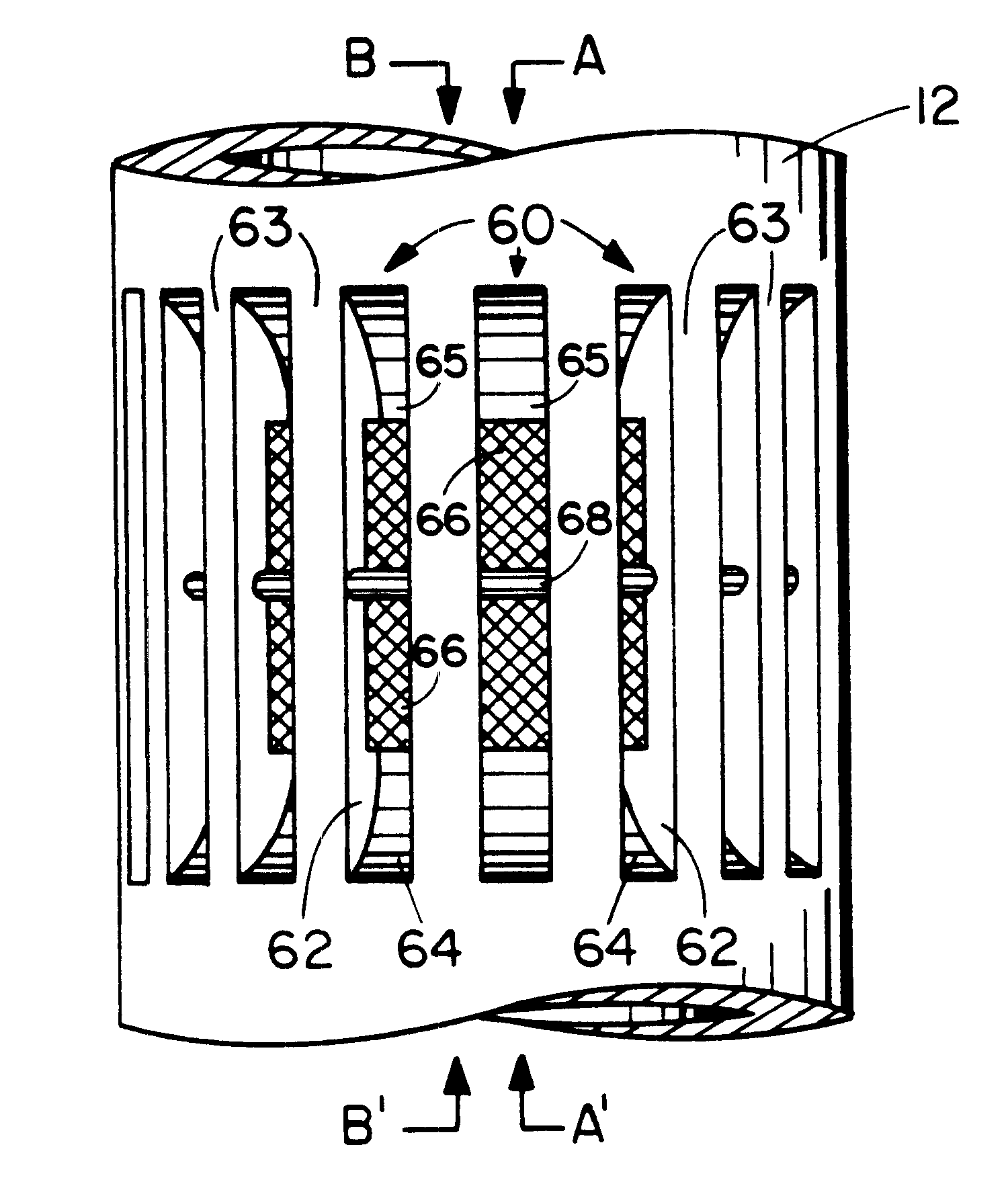
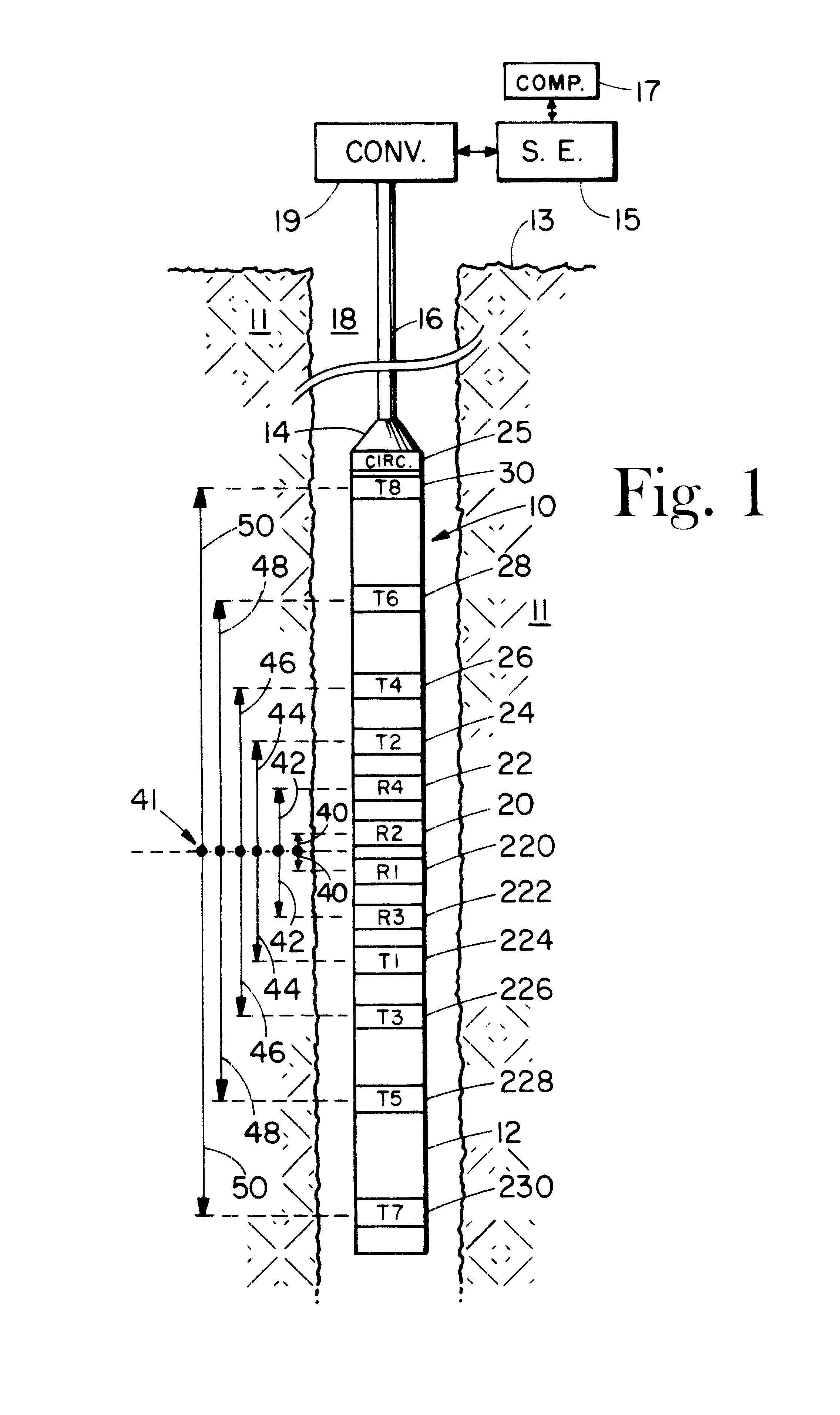
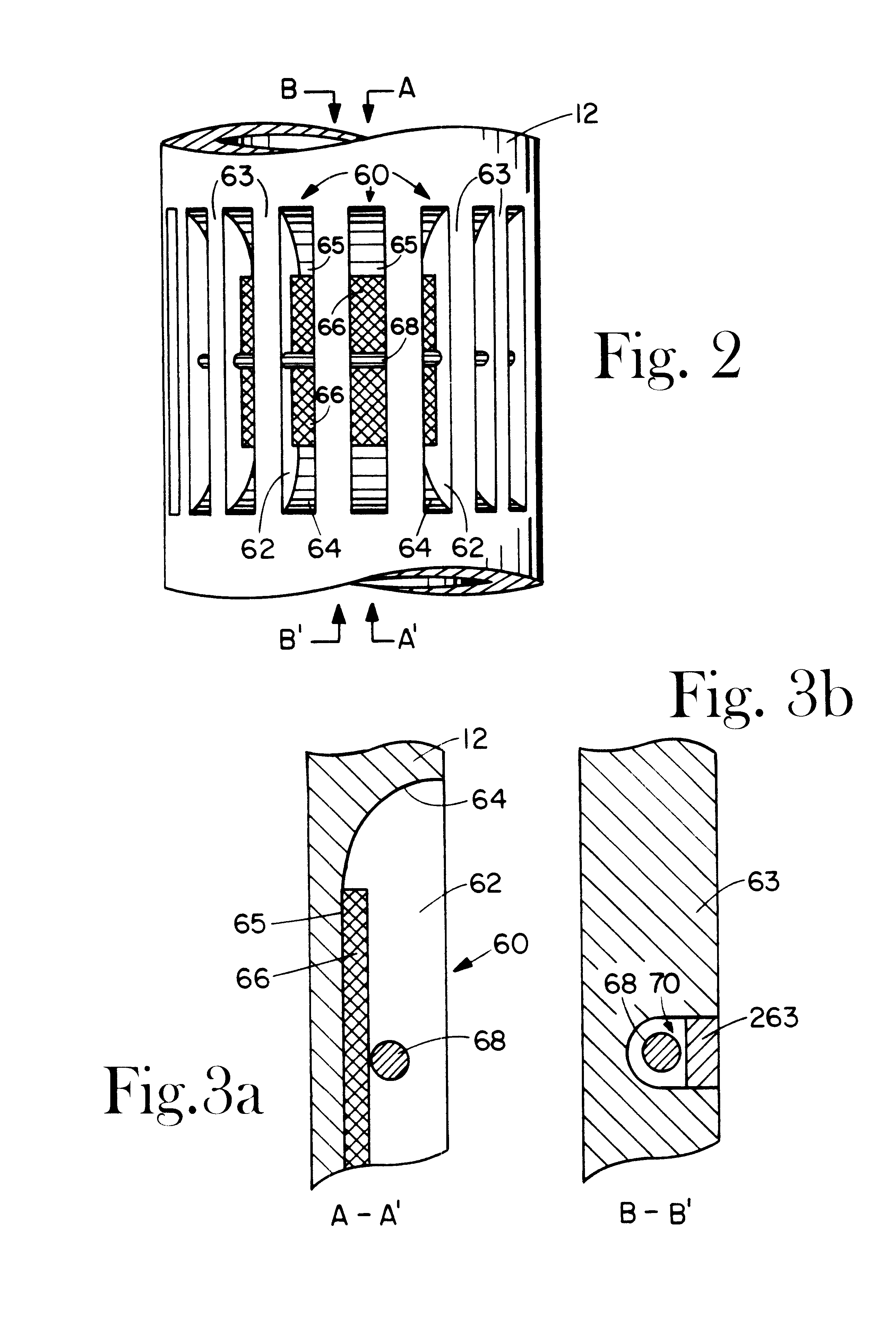
Attention is directed to FIG. 1 which conceptually illustrates the EWP resistivity logging system deployed within a well borehole 18 penetrating an earth formation 11. The tool portion of the system is denoted as a whole by the numeral 10 and comprises a tubular pressure housing 12 and a plurality of transmitter-receiver groups consisting of a total of eight transmitters and four receivers disposed axially and symmetrically about a reference point 41 on the tool. Transmitters T7 and T8, identified at 230 and 30, respectfully, are axially spaced a distance 50 on opposing sides of the reference point 41. Transmitters T5 and T6, identified at 228 and 28, respectfully, are axially spaced a distance 48 on opposing sides of the reference point 41. Transmitters T3 and T4, identified at 226 and 26, respectfully, are axially spaced a distance 46 on opposing sides of the reference point 41. Transmitters T1 and T2, identified at 224 and 24, respectfully, are axially spaced a distance 44 on opp...


PUM


Abstract

An electromagnetic wave propagation resistivity borehole logging system comprising multiple groups of electromagnetic transmitter-receiver arrays operating at three frequencies. The borehole logging tool component of the system employs eight transmitters and four receivers. The transmitters and receivers are disposed axially and symmetrically along the major axis of the tool to form four group pairs. Each group pair consists of a transmitter-receiver groups axially and symmetrically on opposing sides of a reference point on the tool. Each, transmitter-receiver group consists of one transmitter assembly and two receiver assemblies. Each transmitter-receiver group is operated at two of three operating frequencies which are 100 kHz, 400 kHz and 2 MHz. Some of the transmitter and receiver assemblies are fabricated to yield azimuthally focused resistivity measurements, and to yield vertical and horizontal resistivity in anisotropic dipping beds. The system can be embodied as a logging-while-drilling system or as a wireline logging system.

Description

BACKGROUND OF THE INVENTION1. Field of the InventionThis invention is related to measurement of formation properties penetrated by a well borehole, and more particularly related to an electromagnetic wave propagation resistivity well logging system comprising multiple groups of electromagnetic transmitter-receiver arrays operating at three frequencies, with the lowest frequency being about 100 kHz. The system can be embodied to yield horizontal, vertical, azimuthally symmetrical, and azimuthally asymmetrical resistivity measurements with respect to the axis of the borehole.2. Background of the ArtEarth formation resistivity is an important parameter in delineating hydrocarbon and saline water content within the pore space of the formation. Formations containing hydrocarbon in the pore space are typically more resistive than formations of the same lithology and porosity containing saline water in the pore space. Resistivity measurements are typically made by conveying an instrument o...

Claims


Application Information

Patent Timeline
Patent Type & Authority Patents(United States)
IPC IPC(8): G01V3/30G01V3/18
CPCG01V3/30
Inventor THOMPSON, LARRY W.WISLER, MACMILLIAN M.WU, JIAN-QUN
Owner WEATHERFORD TECH HLDG LLC
Why Eureka
Try Eureka