Eureka AIR delivers breakthrough ideas for toughest innovation challenges, trusted by R&D personnel around the world.

Electronically-Controlled Tankless Water Heater with Pilotless Ignition

a technology of electric control and water heater, which is applied in the direction of fluid heater, multi-burner assembly, combustion process, etc., can solve the problems of reducing the efficiency of water heaters, destroying equipment, and increasing equipment costs, so as to minimize the heat loss to the exterior of the area, avoid overheating the water inside the equipment, and maximize gas fuel economy

Inactive Publication Date: 2014-01-09
CALENTADORES DE AMERICA S DE R L DE C V
View PDF3 Cites 7 Cited by
  • Summary
  • Abstract
  • Description
  • Claims
  • Application Information

AI Technical Summary

Benefits of technology

This invention is a water heater that is designed to be safe, efficient, and economical. It includes a corrosion-resistant tank with a multi-burner combustion chamber at the bottom to minimize heat loss. A fin-type heat exchanger captures most of the heat from the combustion gases and transfers it to the water in the tank. A powerful burner is supplied by gas from an electrovalve system. A bimetallic temperature detector prevents overheating. Two temperature sensors measure the water temperature at the inlet and outlet, respectively. An electronic controller sends current to a spark generator to ignite the burner. A screen allows the user to observe the water heater's status. This invention allows the water heater to operate safely and efficiently without a permanently lit pilot light.

Problems solved by technology

The technical problem addressed by this patent is the need for a water heater that can provide consistent hot water without requiring a minimum amount of fluid circulation (hydraulic pressure) while also being able to handle various types of hydraulic networks and prevent fouling on its surfaces. Current options like fast recovery tankless heaters have limitations such as having low tolerance towards extreme temperatures and difficulty handling high levels of salinity in the water.

Method used


Image

  • Electronically-Controlled Tankless Water Heater with Pilotless Ignition
  • Electronically-Controlled Tankless Water Heater with Pilotless Ignition
  • Electronically-Controlled Tankless Water Heater with Pilotless Ignition

Examples


Embodiment Construction

[0017]Reference is now made to particular embodiments of the invention, one or more examples of which are illustrated in the drawings. Each embodiment is provided by way of explanation of the invention, and not as a limitation of the invention. For example, features illustrated as described as part of one embodiment may be used with another embodiment to yield still a further embodiment. It is intended that the present invention include these and other modifications and variations.

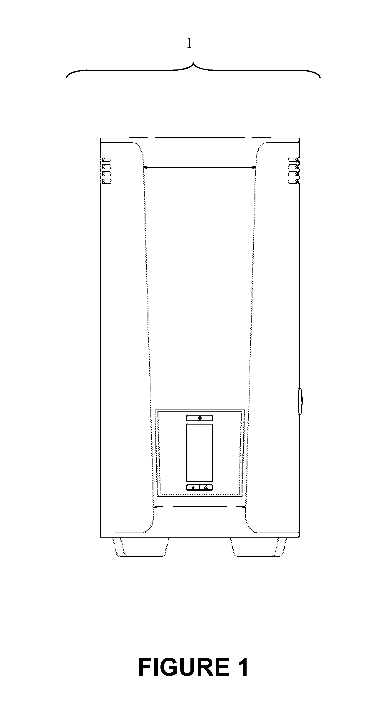
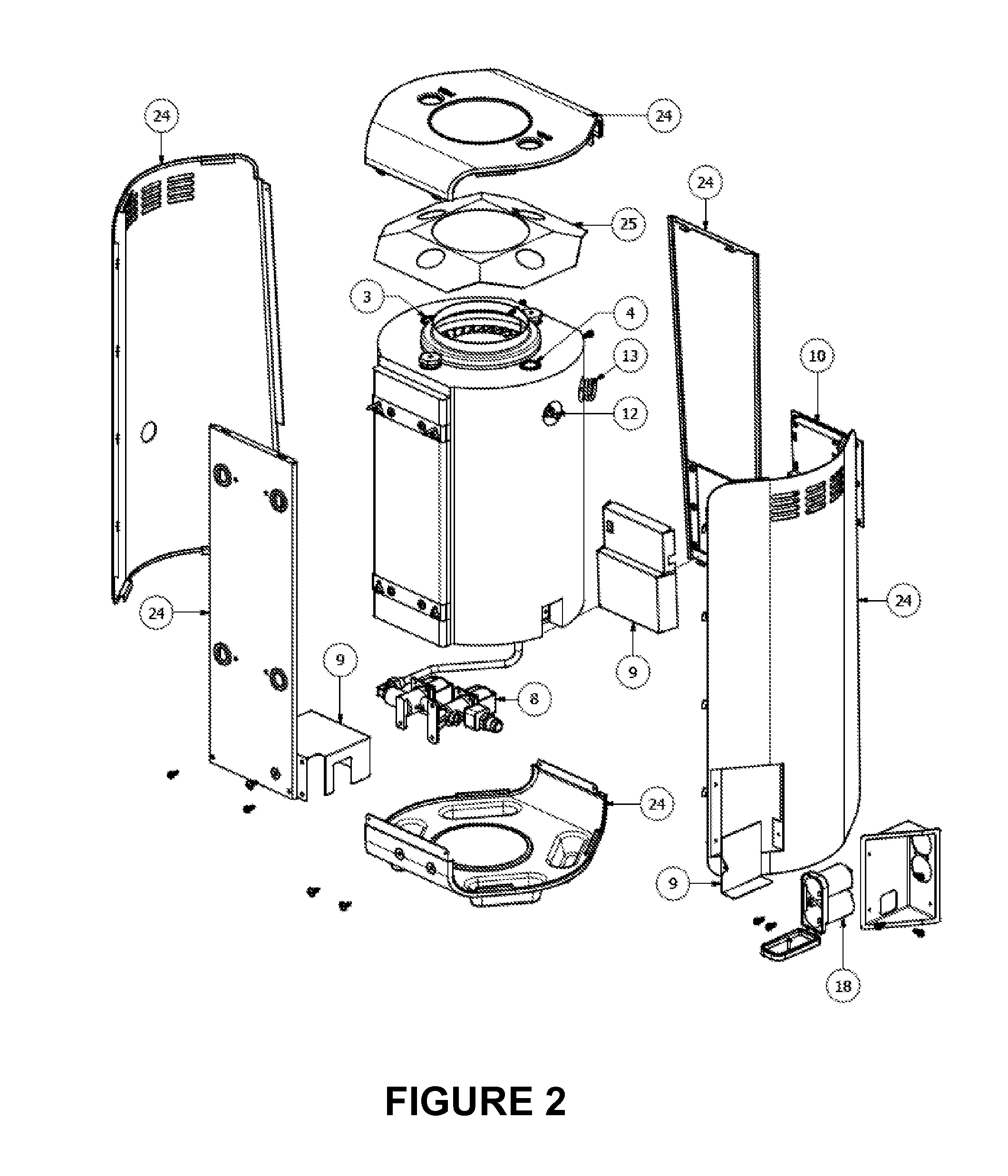
[0018]This invention's water heater (1) shown in FIG. 1 is designed to withstand a pressure greater than 1.0 MPa. The steel water tank (2) is porcelainized on the areas in contact with water to prevent corrosion.

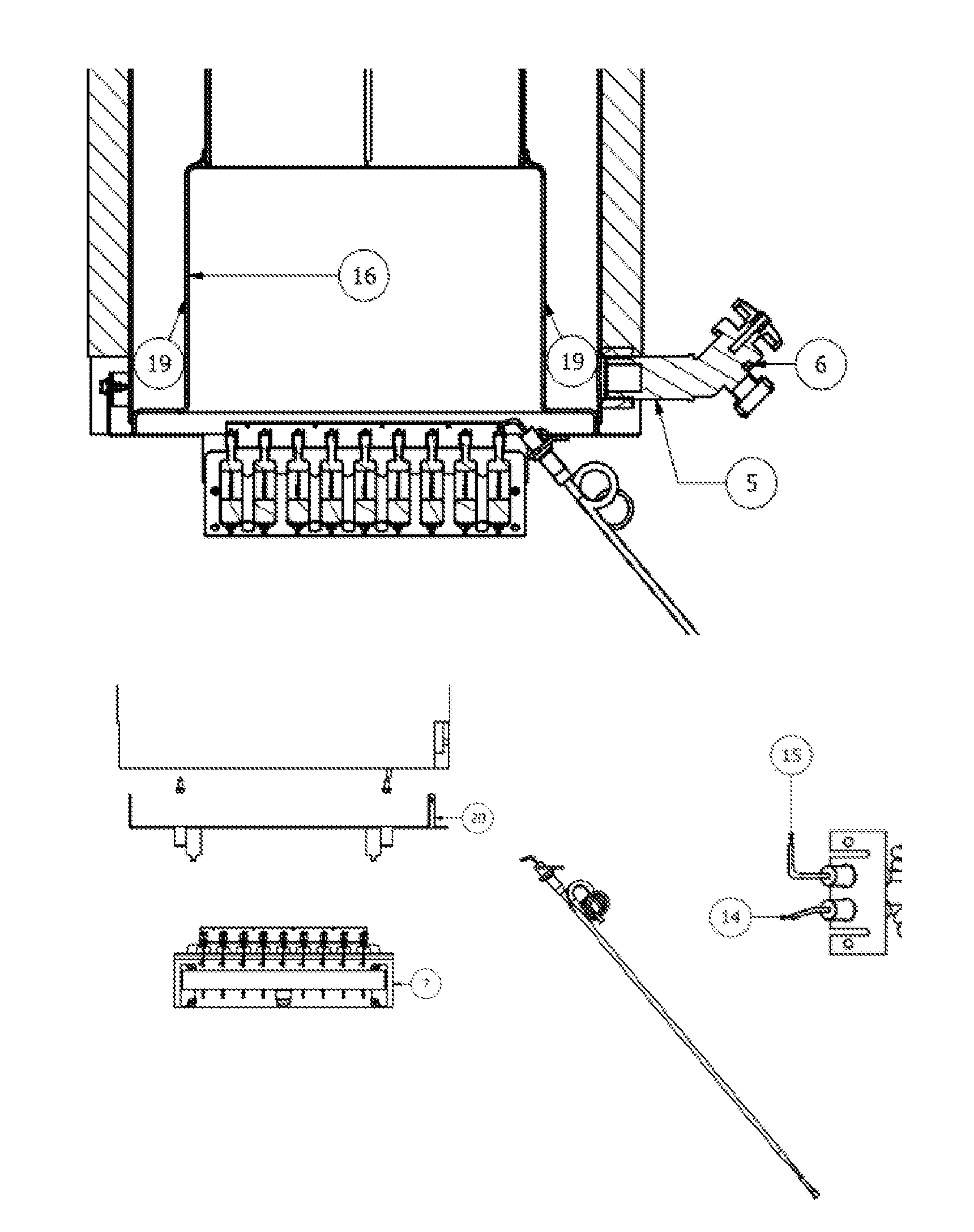
[0019]The cold water inlet (3) is located to the upper-right of the water tank (2), likewise, the hot water outlet (4) is located at the upper left of the tank (2). Additionally, on the lower part of the water tank (2), there is a coupling that connects the water tank (2) to the exterior, allowing ...


PUM


Abstract

A rapid recovery tankless water heater operates by means of an electronic controller or card that regulates the operation of each of the system components, thereby optimizing gas consumption and minimizing the emission of gas pollutants. A multi-burner only ignites when certain conditions or predefined requirements in the electronic controller logic are met. Other factors contributing to improved water heater efficiency are: a) the water tank design which at the bottom has a water chamber surrounding the combustion chamber, and b) the use of a finned heat exchanger, which together with a core, successfully utilizes most of the thermal energy contained in the combustion gases. An air deflector device stops the entry of air currents at the top of the heater, thus stopping potential flame reversing and even flame extinction in the multi-burner.

Description


Claims


Application Information

Patent Timeline
Owner CALENTADORES DE AMERICA S DE R L DE C V
Why Eureka
Eureka Blog
Learn More