
Eureka
For R&D, Eureka makes reading and utilizing patents & technical documents easy.
Eureka AIR
Designed for self-driven R&D workflows. Generate viable solutions, solve complex R&D challenges, empower your innovation with AI.

Eureka Materials
Designed for material experts only. Revolutionize your material R&D, from search, analyze, to developing new materials.

TechResearch
Generate reliable direction feasibility study reports for your R&D in just a few steps.

TechSeek
Discover and master advanced knowledge NOW. Basics, ideas, possibilities, all at once.

TechMind
As an expert in R&D Theories, TechMind can generates customized viable solutions instantly.

TechRisk
Analyze your overall solution with one click, know your potential R&D risks in advance.

TechMonitor
Get weekly tech updates, stay abreast of the latest tech innovations and key insights.
Hemostasis sensor and method of use thereof
- Summary
- Abstract
- Description
- Claims
- Application Information
AI Technical Summary
Benefits of technology
Problems solved by technology
Method used
Image

Examples
example 1
A. Example 1
FIGS. 9a Though 9c
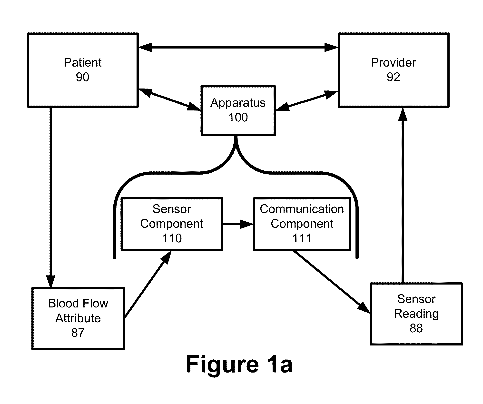
[0257]FIG. 9a is a diagram illustrating a front view of a hemostasis band 100 that includes a body component 102, a padding component 106, a fastener component 104, a pressure component 108. To that underlying framework, a wide variety of different sensor components 110 and communication components 111 could be added to as an integrated device.
[0258]FIG. 9b is a diagram illustrating an example of perspective view of the hemostasis band apparatus 100 illustrated in FIG. 9a.
[0259]FIG. 9c is a diagram illustrating an example of a side view of the hemostasis band apparatus 100 illustrated in FIG. 9a.
example 2
B. Example 2
FIGS. 10a Though 10d
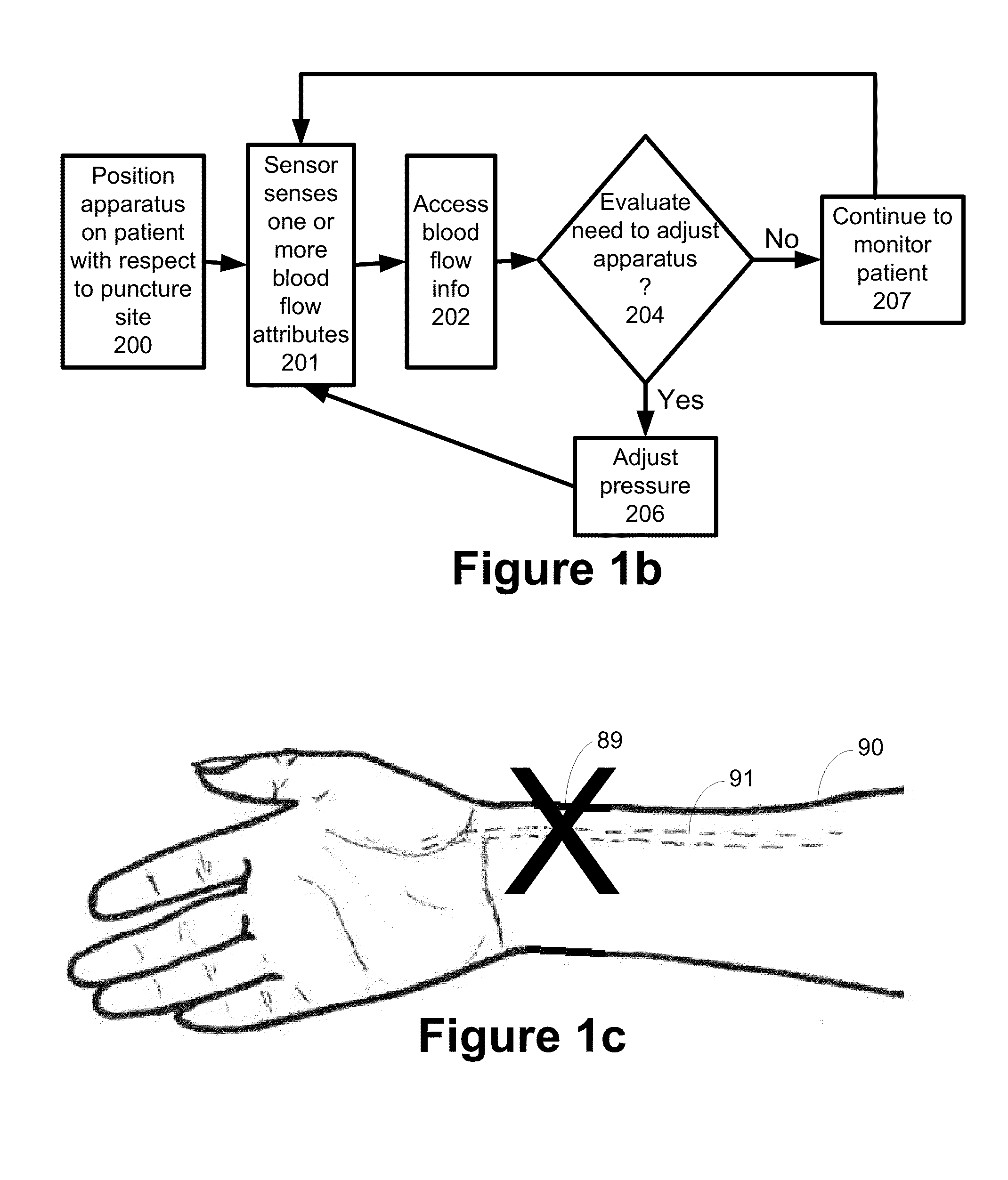
[0260]FIG. 10a is a diagram illustrating an example of a front view of an integrated hemostasis sensor apparatus 100 with a film 120 as a sensor component 110, and an inflatable balloon as a pressure component 108. The film 120 is positioned between the pressure component 108 and the radial artery 91 of the patient 90. The apparatus 102 also includes a fastener component 120 in the form of two ®VELCRO strips.
[0261]FIG. 10b is a diagram illustrating an example of a side view of the integrated hemostasis sensor apparatus 100 illustrated in FIG. 10a. This illustration shows the two fastener components 104 locked together so that the body component 102 forms a loop.
[0262]FIG. 10c is a diagram illustrating an example of a side view of the hemostasis band illustrated in FIG. 10a. In FIG. 10c, an adhesive component 115 is located between the pressure component 108 and the film 120 to securely the position the film 120 on the pressure component 108.
[0263]FIG...
example 3
C. Example 3
FIGS. 11a-11f
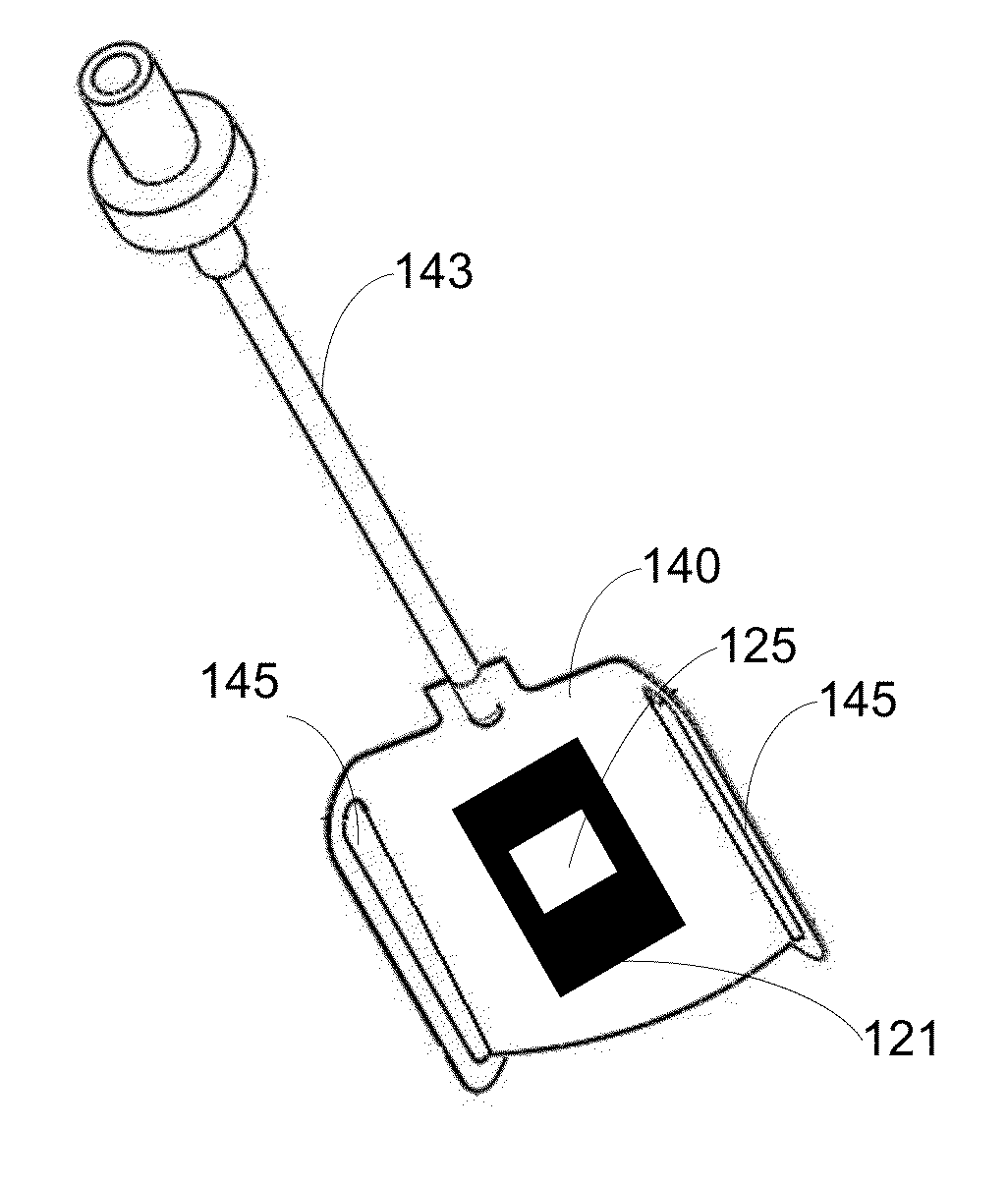
[0264]FIG. 11a is a diagram illustrating an example of a side view of a sensor apparatus 100 embodied in an integrated hemostasis band. This embodiment of the apparatus 100 utilizes the subassembly illustrated in FIG. 5e that is discussed above. Two fastener components 104 comprised of interlocking clasps can open and close the apparatus 100. The body component 102 is a semi-rigid / semi-flexible band 134 that is substantially transparent. A balloon 140 is the pressure component 108 and the balloon 140 also serves a sensor enhancement component 114. Two gaps 145 on the balloon 140 allow the balloon 140 to slide along the body component 102. An inlet 143 provides for air to be added or released from the balloon 140.
[0265]FIG. 11b is a diagram illustrating an example of a perspective view of the apparatus 100 illustrated in FIG. 11a. FIG. 11c is diagram illustrating an example of the apparatus of FIGS. 11a and 11b, but from a different perspective view. FIG. 11...
PUM
 Abstract
Description
Claims
Application Information
 - R&D Engineer
- R&D Manager
- IP Professional
- Industry Leading Data Capabilities
- Powerful AI technology
- Patent DNA Extraction
Browse by: Latest US Patents, China's latest patents, Technical Efficacy Thesaurus, Application Domain, Technology Topic, Popular Technical Reports.
© 2024 PatSnap. All rights reserved.Legal|Privacy policy|Modern Slavery Act Transparency Statement|Sitemap|About US| Contact US: help@patsnap.com