Outer shell member positioning device

a positioning device and outer shell technology, applied in the direction of keyhole guards, building locks, constructions, etc., can solve the problems of sliding hook design low stability and sliding hook members that can be forced out of the hooked position, and achieve high structural stability, facilitate operation, and high level of security

Active Publication Date: 2014-01-16
CHENBRO MICOM
View PDF10 Cites 9 Cited by
  • Summary
  • Abstract
  • Description
  • Claims
  • Application Information

AI Technical Summary

Benefits of technology

[0007]The present invention has been accomplished under the circumstances in view. It is therefore the main object of the present invention to provide an outer shell member positioning device, which comprises a mounting base member, which is mounted at an outer shell member and which comprises two pivot holders located at one end thereof and holding a pivot pin therebetween and a retaining hole located at an opposite end thereof, a bracket, which comprises two constraint bars obliquely disposed at one end there and pivotally coupled to the pivot pin of the mounting base member for engaging into a locating hole in an inner shell member to secure the outer shell member to the inner shell member and box track disposed at an opposite end thereof, a spring-loaded sliding hook member, which comprises two forwardly extending first hook bars slidably hooked in respective sliding slots in two opposite lateral sides of the box track and a downwardly extending second hook bar for hooking in the retaining hole of the mounting base member to hold the bracket in an accommodation open chamber inside the mounting base member, and a locking device mounted in the bracket for locking the sliding hook member in the hooked position to provide an anti-theft effect.
[0008]According to another aspect of the present invention, when the locking device is rotated with the key to move a locking latch thereof from the locking position to the unlocking position, the sliding hook member is released from the constraint of the locking latch and can be moved in the box track to compress the loaded spring thereof and to disengage its second hook bar from the retaining hole of the mounting base member, allowing the bracket to be turned about the pivot pin to the outside of the accommodation open chamber of the mounting base member to release the inner shell member from the constraint of the constraint bars of the bracket. At this time, the outer shell member can be removed from the inner shell member. Thus, the outer shell member positioning device has a high level of structural stability and facilitates operation.
[0009]According to still another aspect of the present invention, when the outer shell member is mounted to the inner shell member, the user simply needs to bias the bracket toward the inside of the accommodation open chamber of the mounting base member to force the constraint bars into engagement with the locating hole of the inner shell member. At this time, the second hook bar of the sliding hook member will be automatically forced into engagement with the retaining hole of the mounting base member to secure the bracket positively in position, and the constraint bars of the bracket are prohibited from being forced out of the locating hole of the inner shell member by a shearing force as the outer shell member is being pulled accidentally by an external force.
[0010]According to still another aspect of the present invention, when the locking device is rotated to the locking position with the key, the locking latch of the locking device is stopped against the base plate of the sliding hook member to prohibit movement of the sliding hook member toward the inside of the box track of the bracket, keeping the second hook bar of the sliding hook member in positive engagement with the retaining hole of the mounting base member, assuring a high level of security.

Problems solved by technology

However, this sliding hook design has low stability.
The sliding hook members can be forced out of the hooked position accidentally during delivery of the server or electronic equipment.
Further, due to lack of anti-theft measures, an evil person can easily open the server case or outer shell member of the server or electronic equipment to steal the internal electronic component parts or storage data of the server or electronic equipment.

Method used


Image

  • Outer shell member positioning device
  • Outer shell member positioning device
  • Outer shell member positioning device

Examples


Embodiment Construction

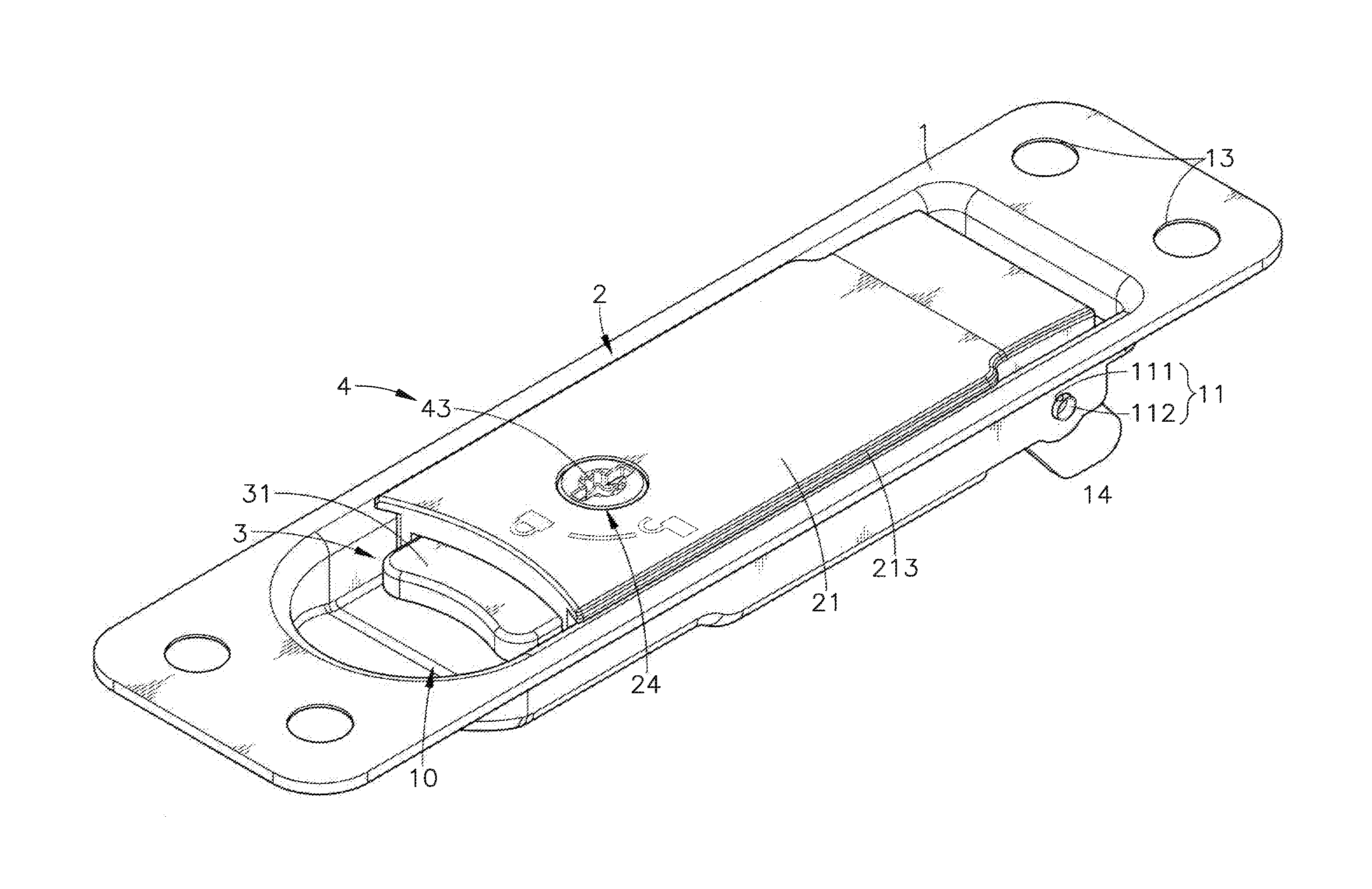
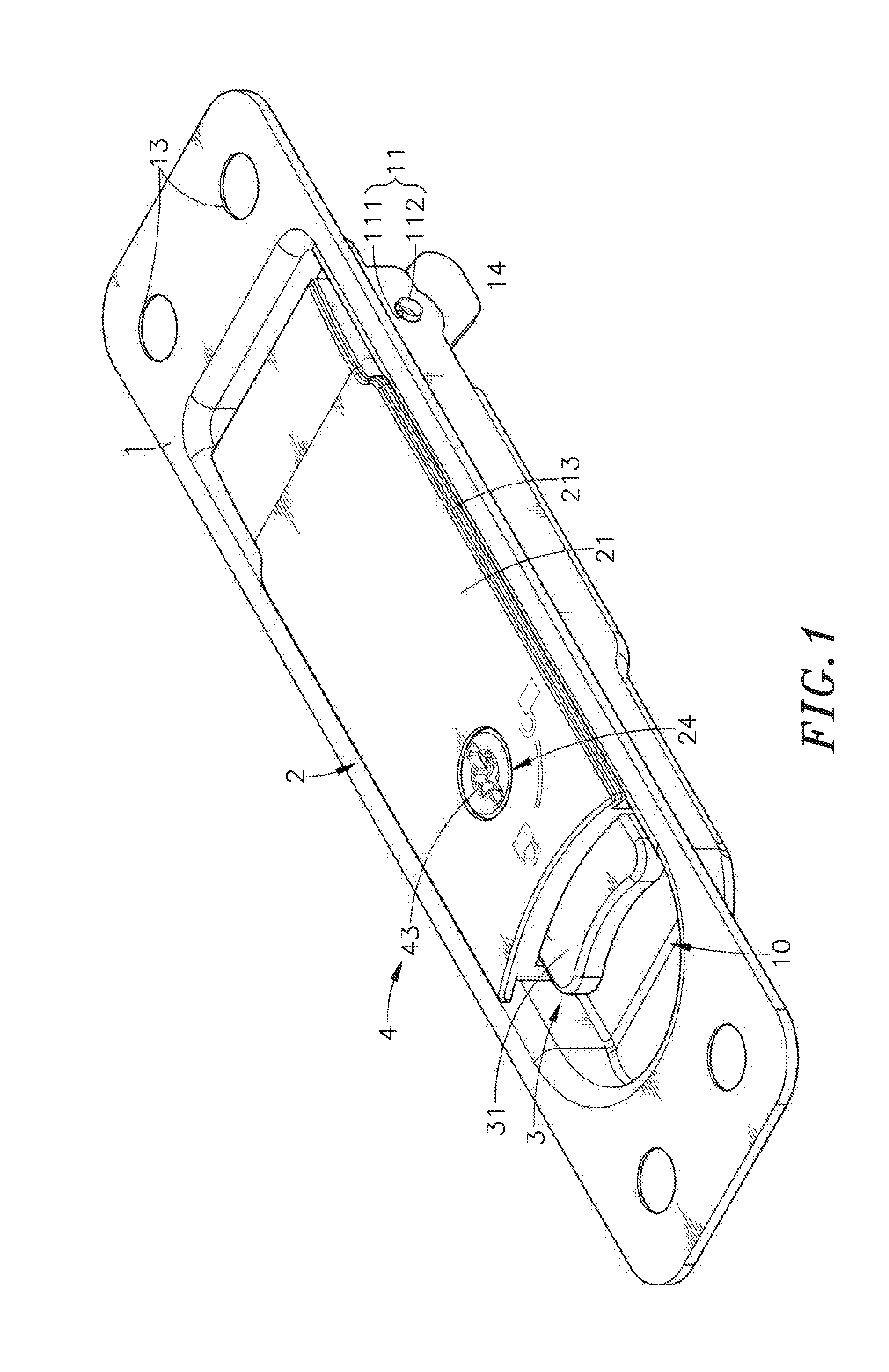
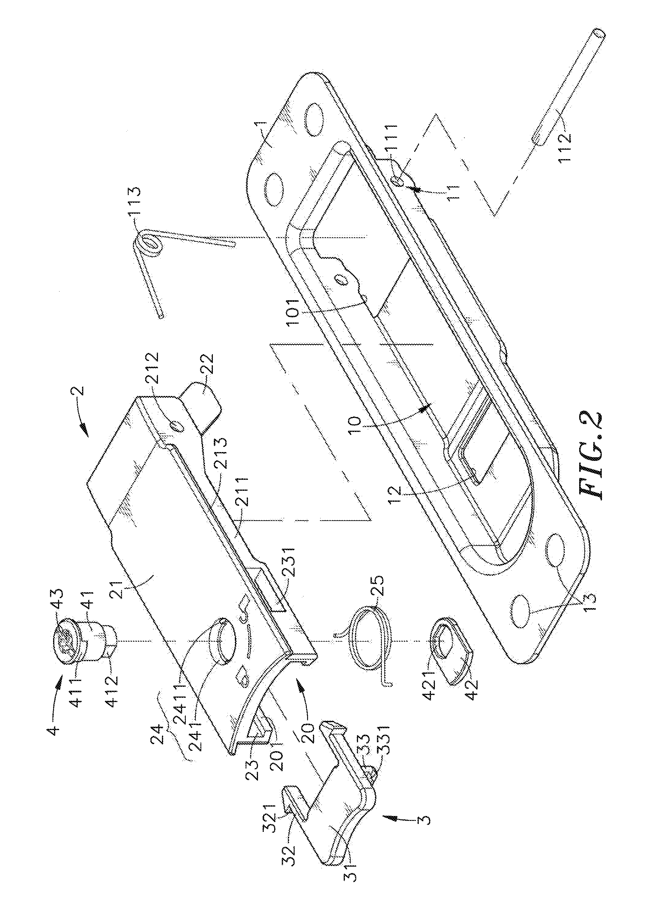
[0019]Referring to FIGS. 1-4, an outer shell member positioning device in accordance with the present invention is shown. The outer shell member positioning device comprises a mounting base member 1, a bracket 2, a sliding hook member 3, and a locking device 4.

[0020]The mounting base member 1 defines an elongated accommodation open chamber 10, an opening 101 cut through a bottom wall thereof and disposed in communication with one end of the accommodation open chamber 10, pivoting means, for example, two pivot holders 11 downwardly extended from the bottom wall and arranged at two opposite lateral sides of the first opening 101 in a parallel manner and defining therein a respective pivot hole 111, a pivot pin 112 inserted into the pivot holes 111 of the pivot holders 11, a torsion spring 113 mounted on the pivot pin 112, a retaining hole 12 cut through the bottom wall and disposed in communication with an opposite end of the accommodation open chamber 10, and mounting portions, for e...


PUM


Abstract

An outer shell member positioning device includes a mounting base member mounted at an outer shell member, a bracket pivotally coupled to the mounting base member and biasable between a first position where constraint bars of the bracket are engaged in a locating hole of an inner shell member to stop the inner shell member in place and a second position where the inner shell member is released from the constraint of the constraint bars and movable out of the outer shell member, a sliding hook member mounted in one end of the bracket and hookable to the mounting base member to secure the bracket in the first position, and a locking device mounted in the bracket and operable to lock the sliding hook member to the mounting base member.

Description

[0001]This application claims the priority benefit of Taiwan patent application number 101213322, filed on Jul. 10, 2012.BACKGROUND OF THE INVENTION[0002]1. Field of the Invention[0003]The present invention relates to shell member mounting technology and more particularly, to an outer shell member positioning device, which comprises a mounting base member mounted at an outer shell member, a bracket pivoted to the mounting base member and engageable into a locating hole of an inner shell member to stop the inner shell member inside the outer shell member in place, a sliding hook member slidably mounted in one end of the bracket and hookable in a retaining hole of the mounting base member to hold the bracket in engagement with the inner shell member, and a locking device mounted in the bracket for locking the sliding hook member.[0004]2. Description of the Related Art[0005]As the coming of the information era, various electronic products have entered our life. With the continuous deve...

Claims


Application Information

Patent Timeline
Patent Type & Authority Applications(United States)
IPC IPC(8): E05B65/00
CPCE05B65/006E05B5/00E05B13/10E05C3/047Y10T70/5389Y10T70/5562Y10T70/5761Y10T292/57
Inventor YANG, CHENG-FENG
Owner CHENBRO MICOM
Why Eureka
Try Eureka