Multiphase Flowmeter and Liquid Film Measurement Method

Inactive Publication Date: 2014-01-16
SCHLUMBERGER TECH CORP
View PDF4 Cites 12 Cited by
  • Summary
  • Abstract
  • Description
  • Claims
  • Application Information

AI Technical Summary

Benefits of technology

The patent describes a method and device for measuring the flow rate of a multiphase fluid mixture in a pipe section. The method involves using ultrasonic sensors to estimate the characteristics of a liquid film along the wall of the pipe section and correcting the estimated gas and liquid phases based on these characteristics when gas flows in the core of the pipe section and the liquid film flows partially along the wall and partially in the core. The device can also measure the degree of annularity of the multiphase fluid mixture in the flow meter. The ultrasonic sensors are non-intrusive and securely fit the pipe without introducing any source of fluid leakage. The technical effects of this patent are improved accuracy of measuring flow rate and degree of annularity of multiphase fluid mixtures in a pipe section.

Problems solved by technology

In reality, however, depending on where the multiphase flow meter is installed the incoming multiphase flow mixture is not necessarily homogenous.
The efficiency of a flow conditioner is not always perfect, resulting in a less homogeneous flow mixture in the flow meter.
If the degree of homogeneity of the flow mixture at the inlet or inside the multiphase flow meter becomes too low, or the degree of separation between respective phases of the flow mixture becomes too low, then the relevant flow modeling approach is less accurate or no longer applicable.
Furthermore, the relation between flow rate and pressure drop within the measuring section of the Venturi cannot be modeled correctly.
As a consequence, limitations on the accuracy of such a multiphase flow rate measurements may occur when the multiphase fluid mixture is not distributed according to the predetermined modeling approach.
Further limitations on the accuracy may occur when a homogenous based flow modeling approach is applied when the amount of one or several phases of the mixture becomes very low.
Indeed, in this case a proper flow conditioning of the multiphase fluid mixture is not guaranteed.
The split of liquid between the gas core and the pipe wall is difficult, if not impossible, to predict with the current instrumentation technology implemented in differential pressure-based flow meters.

Method used


Image

  • Multiphase Flowmeter and Liquid Film Measurement Method
  • Multiphase Flowmeter and Liquid Film Measurement Method
  • Multiphase Flowmeter and Liquid Film Measurement Method

Examples


Embodiment Construction

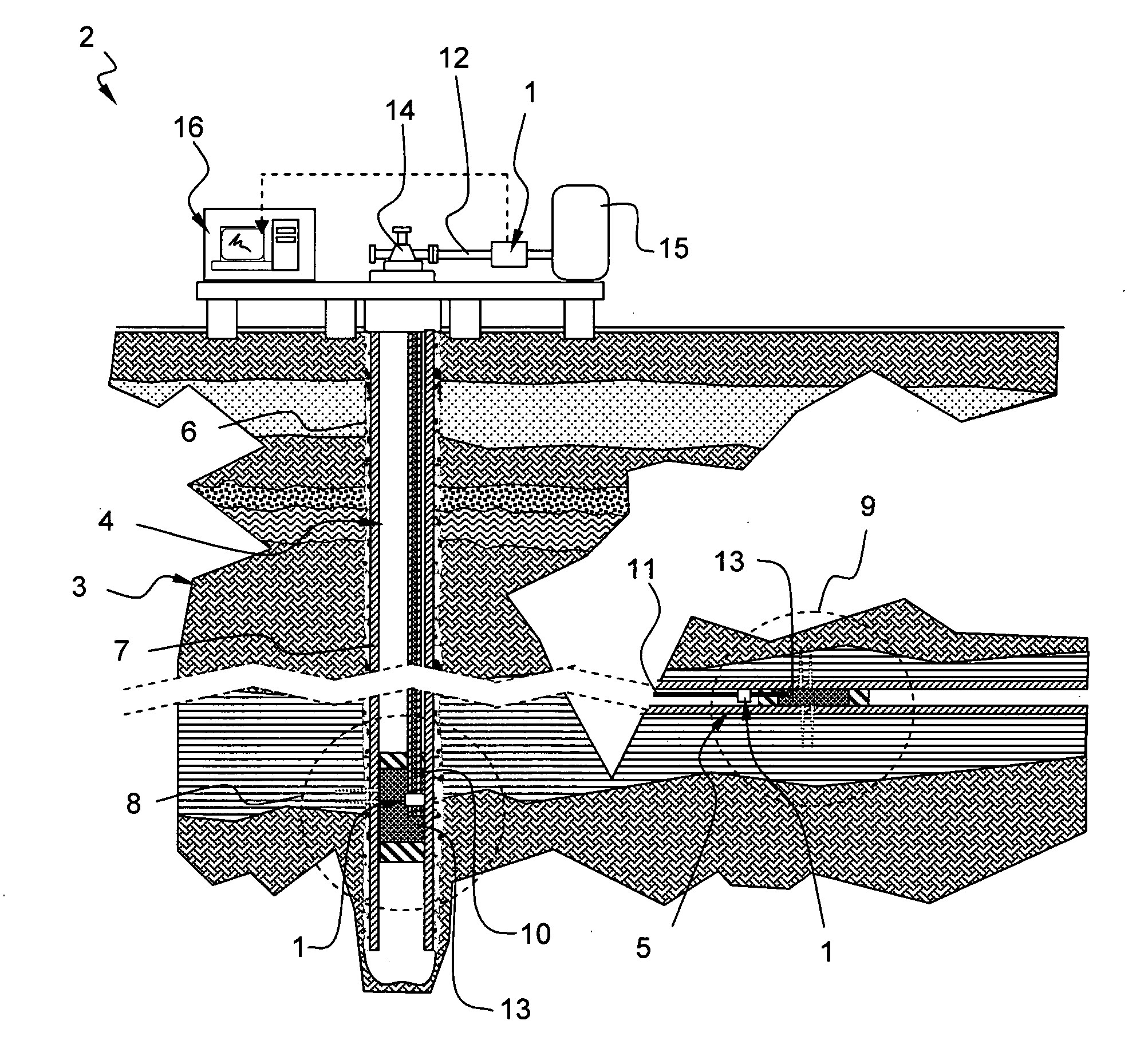
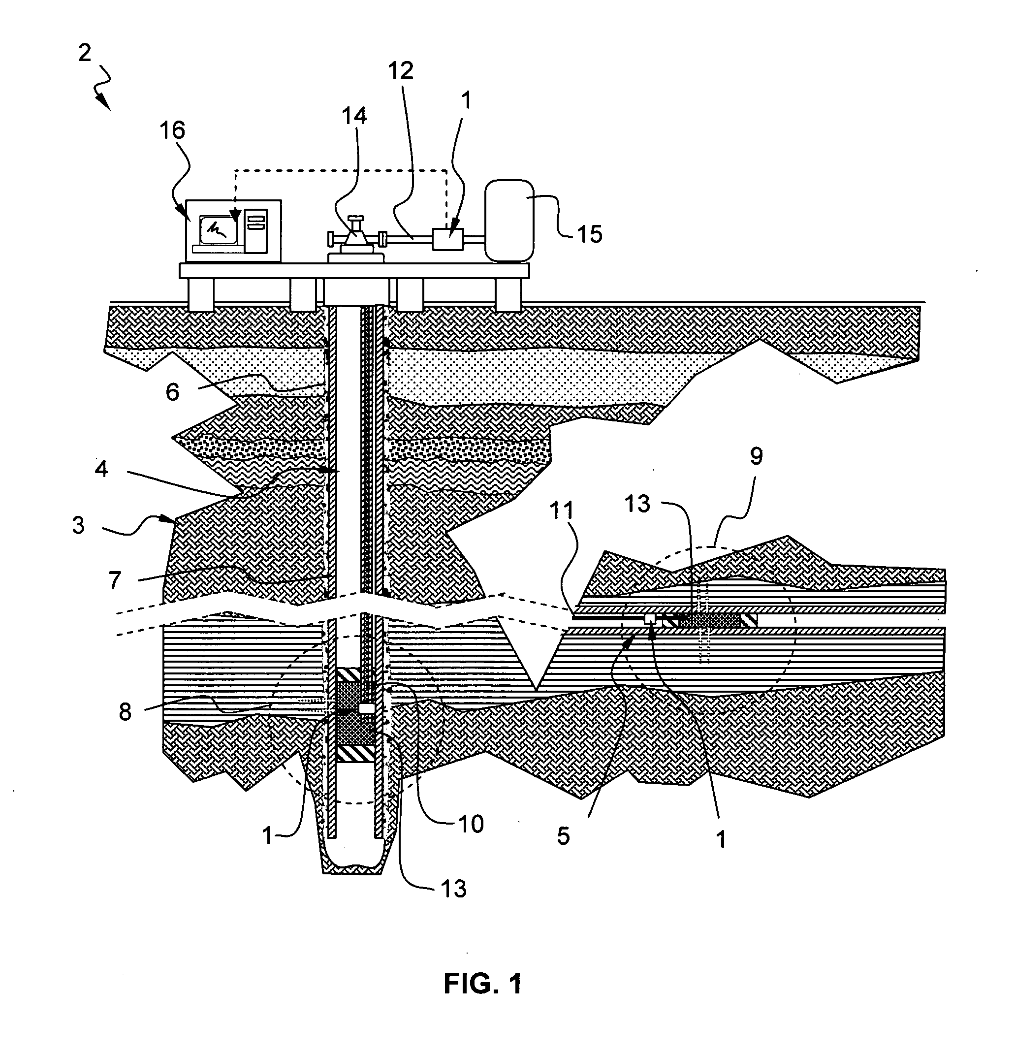
[0028]FIG. 1 schematically shows an onshore hydrocarbon well location and equipment 2 above a hydrocarbon geological formation 3 after a drilling operation has been carried out, after a drill pipe has been run, and eventually, after cementing, completing and perforating operations have been carried out, and exploitation has begun. The well is beginning to produce hydrocarbon, e.g. oil and / or gas. At this stage, the well bore comprises a substantially vertical portion 4, and may also comprise horizontal or deviated portions 5. The well bore 4 is either an uncased borehole, or a cased borehole, or a mix of uncased and cased portions.

[0029]The cased borehole portion comprises an annulus 6 and a casing 7. The annulus 6 may be filled with cement or an open-hole completion material, for example gravel pack. Downhole, a first 8 and second 9 producing sections of the well typically comprise perforations, production packers and production tubings 10, 11 at a depth corresponding to a reservoi...


PUM


Abstract

A flow meter apparatus and method are presented for measuring a flow rate of a multiphase fluid mixture comprising at least one gas phase and one liquid phase. The flow meter comprises a pipe section and measurement section through which the mixture flows. The flow meter also comprises a fraction measurement device adapted to estimate a representative fraction of the gas phase and / or liquid phase of the mixture passing at the measurement section. Moreover, the flow meter preferably comprises at least one ultrasonic sensor arranged to estimate a characteristic, such as liquid film thickness or velocity, of a portion of the liquid phase flowing as liquid film along a wall of the pipe section. The characteristic is preferably used to correct the estimated representative fraction of the gas phase and / or liquid phase when the gas phase flows in a core of the pipe section, and a portion of the liquid phase flows partially as liquid film along the wall of the pipe section and another portion of the liquid phase flows partially as liquid droplets in the core of the pipe section.

Description

TECHNICAL FIELD[0001]An aspect of the present invention relates to a flow meter for measuring a flow rate of a multiphase fluid mixture having at least a gas phase and a liquid phase. Another aspect of the present invention relates to a method for measuring the flow rate of a multiphase fluid mixture and correcting a representative fraction measurement of the gas phase and / or liquid phase using a measurement of the liquid film portion of the liquid phase. Such a flow meter and measurement method may be used, in particular but not exclusively, in oilfield related applications, for example, to measure a flow rate of a hydrocarbon effluent flowing out of a geological formation into a well that has been drilled for the purpose of hydrocarbon exploration and production.BACKGROUND OF THE INVENTION[0002]WO 99 / 10712 describes a flow rate measurement method adapted to oil effluents made up of multiphase fluid mixtures comprising water, oil, and gas. The effluent is passed through a Venturi i...

Claims


Application Information

Patent Timeline
IPC IPC(8): G01F1/74
CPCG01F1/74G01F1/44G01F1/50
Inventor LUPEAU, ALEXANDREBAKER, ANDREW CHARLESCADALEN, SEBASTIENFOURNIER, BENOIT
Owner SCHLUMBERGER TECH CORP
Why Eureka
Try Eureka