Supercharge Your Innovation With Domain-Expert AI Agents!

Flow Stabilizer

a technology of flow stabilizer and stabilizer, which is applied in the direction of mechanical equipment, process and machine control, instruments, etc., can solve the problems of inconvenience for users and achieve the effect of reducing nois

Inactive Publication Date: 2014-01-16
DELTA ELECTRONICS INC
View PDF0 Cites 3 Cited by
  • Summary
  • Abstract
  • Description
  • Claims
  • Application Information

AI Technical Summary

Benefits of technology

The present disclosure provides a flow stabilizer for stabling the output flow rate of a water solenoid valve. The flow stabilizer includes a base and a noise reduction structure, which is curved in shape and located on the base. Additionally, the flow stabilizer may also include at least one narrow hole formed on the base or the noise reduction structure. The technical effect of this disclosure is that it provides a way to stabilize the output flow rate of a water solenoid valve, which can reduce noise and improve the overall performance of the valve.

Problems solved by technology

Therefore, such unstable output flow rate of the water solenoid valve introduces inconvenience for the users.

Method used


Image

  • Flow Stabilizer
  • Flow Stabilizer
  • Flow Stabilizer

Examples


Embodiment Construction

[0030]Reference will now be made in detail to the present embodiments of the disclosure, examples of which are illustrated in the accompanying drawings. Wherever possible, the same reference numbers are used in the drawings and the description to refer to the same or like parts.

[0031]It will also be understood that, although the terms first, second, third, etc. may be used herein to describe various elements, these elements should not be limited by these terms. These terms are only used to distinguish one element from another. For example, a first protrusion structure could be termed a second protrusion structure, and, similarly, a second protrusion structure could be termed a first protrusion structure, without departing from the scope of the present disclosure.

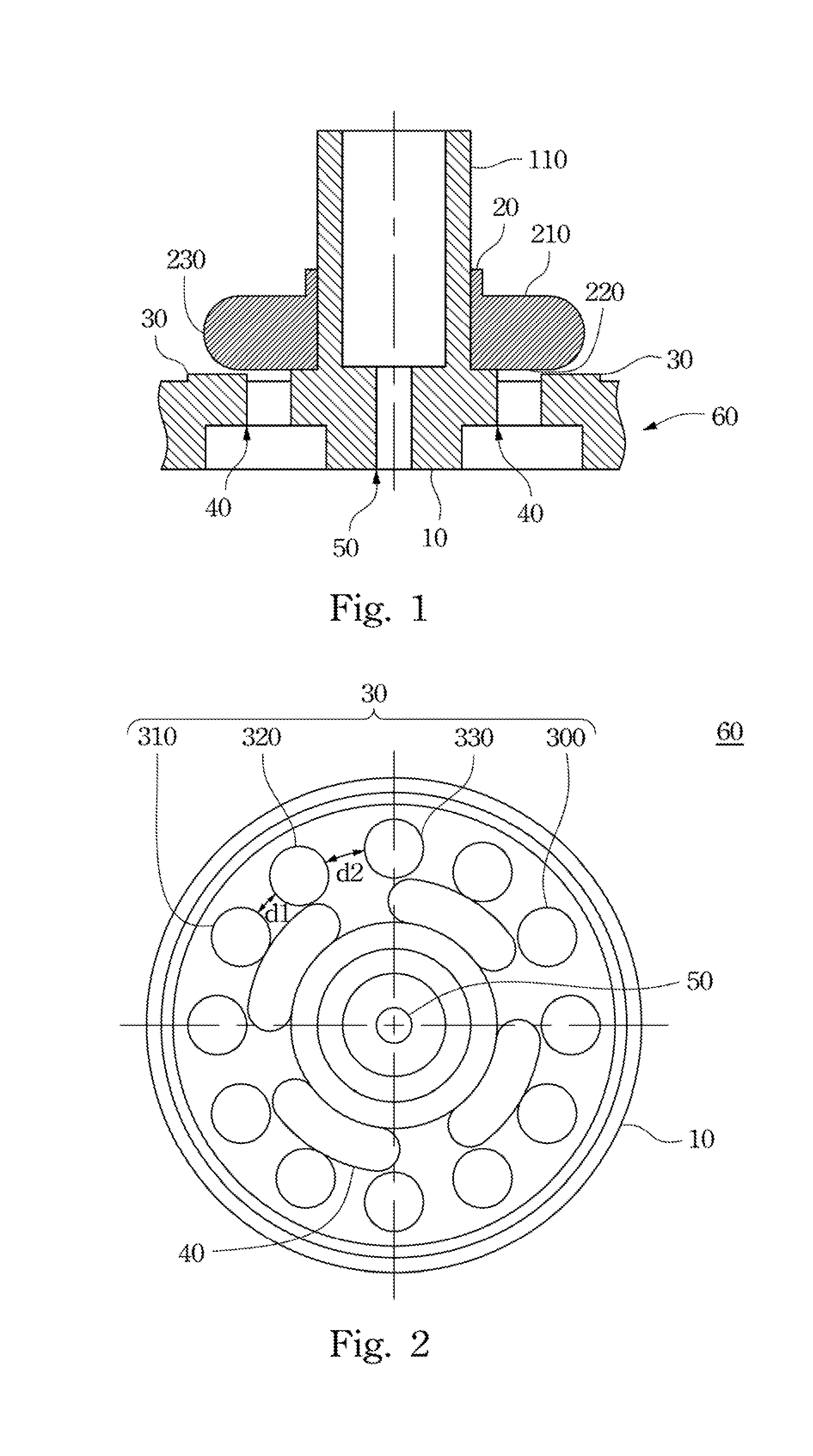
[0032]FIG. 1 is a cross-sectional view of a flow stabilizer in accordance with one embodiment of the present disclosure. As shown in this figure, the flow stabilizer includes a flow guiding body 60 and a noise reduction stru...


PUM


Abstract

A flow stabilizer includes a base and a noise reduction structure. The noise reduction structure is disposed on the base, and it includes a first surface and a second surface. The edges of first surface and the second surface are curved.

Description

RELATED APPLICATIONS[0001]This application claims priority to Taiwan Application Serial Number 101125024, filed Jul. 12, 2012, which is herein incorporated by reference.BACKGROUND[0002]1. Technical Field[0003]Embodiments of the present disclosure relate to a flow stabilizer. More particularly, embodiments of the present disclosure relate to a flow stabilizer used for a water solenoid valve.[0004]2. Description of Related Art[0005]Water solenoid valves have been widely applied in various water supplying devices, such as a water faucet. In a general water solenoid valve, a valve rod is placed in a sliding channel of a base, to be able to slide along the sliding channel. A spring is contained in the sliding channel for applying a pushing force on the valve rod. A coil in the base can be electrically applied to generate magnetic forces contractedly or extendedly adjusting the position of the valve rod, so that the valve rod can be switched to close or open the flow channel of the water ...

Claims


Application Information

Patent Timeline
IPC IPC(8): F15D1/04
CPCE03C1/08E03D2201/20G05D7/0635
Inventor TSAI, MING-CHIHLI, GUAN-HSIENHSUEH, YU-LIN
Owner DELTA ELECTRONICS INC
Features
  • R&D
  • Intellectual Property
  • Life Sciences
  • Materials
  • Tech Scout
  • Unparalleled Data Quality
  • Higher Quality Content
  • 60% Fewer Hallucinations
Learn More