Pavement interface

Inactive Publication Date: 2014-01-16
OATES BEVERLEY ANN
View PDF10 Cites 1 Cited by
  • Summary
  • Abstract
  • Description
  • Claims
  • Application Information

AI Technical Summary

Benefits of technology

[0009]The interface presents a staggered or oblique edge to oncoming traffic, thus rendering the impact with the second surface more gradual (rather than instantaneous). This

Problems solved by technology

This means that co-axial wheels of a vehicle will impact the interface simultaneously, resulting in a substantially instantaneous or impulsive impact.
This im

Method used


Image

  • Pavement interface
  • Pavement interface
  • Pavement interface

Examples


Embodiment Construction

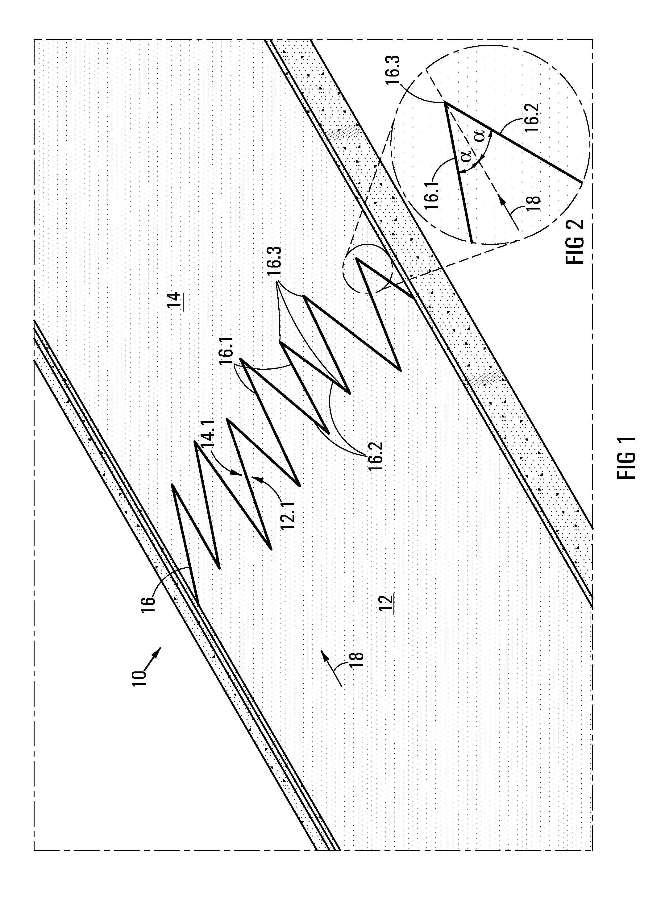
[0025]Referring initially to FIG. 1, reference numeral 10 generally indicates a pavement interface, in accordance with the invention. The pavement interface includes a first section of pavement 12 and a second section of pavement 14, and the interface 10 is between the two sections of pavement 12, 14.

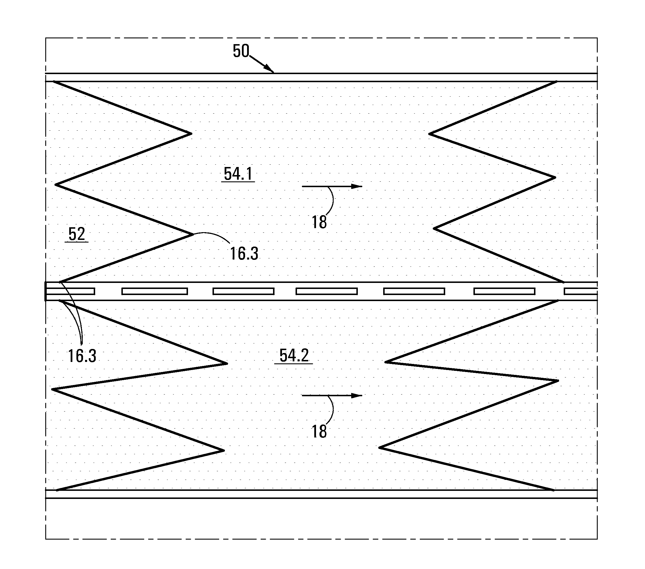
[0026]A trailing (or terminating) edge 12.1 of the first section of pavement 12 has a zigzag shape. Similarly, a leading edge 14.1 of the second section of pavement 14 has a complemental zigzag shape, and it abuts the trailing edge 12.1. Thus, a boundary 16 between the two sections of pavement 12, 14 is zigzag-shaped. The boundary 16 extends in a direction transverse to a direction of traffic flow (generally indicated by arrow 18).

[0027]Referring now also to FIG. 2, the boundary 16 includes (in conventional zigzag fashion) a series of interspaced rising edges 16.1 and falling edges 16.2. Between each adjacent rising and falling edge 16.1, 16.2 is an apex 16.3. Each rising edge 16.1 and ...


PUM


Abstract

Pavement interface (10) and method of creating a pavement interface. The pavement interface (10) includes a first section of pavement (12) having a zigzag-shaped trailing edge (12.1) and a second section of pavement (14) having a complemental zigzag-shaped leading edge (14.2) which abuts the trailing edge (12.1) of the first section of pavement (12). Thus, a boundary between the two sections (12, 14) of pavement is zigzag-shaped.

Description

FIELD OF INVENTION[0001]The invention relates generally to pavements or road surfaces, and specifically to a pavement interface.BACKGROUND OF INVENTION[0002]The Inventor is aware that pavements are sometimes required to transition from one surface to another. For instance, in pavement re-surfacing, the pavement may transition from the old surface to the new surface (or vice versa). Similarly, it is sometimes required to dig trenches in the pavement to lay cables or pipes. The trench is then re-surfaced.[0003]The interface from one surface to another is almost always linear and usually perpendicular to a direction of traffic flow. This means that co-axial wheels of a vehicle will impact the interface simultaneously, resulting in a substantially instantaneous or impulsive impact. While the profile of the interface is as flat as possible to minimise this impact on the wheels, there is often still at least a small ridge or depression. This impact is noisy, and causes a shock both in the...

Claims


Application Information

Patent Timeline
IPC IPC(8): E01C11/02
CPCE01C11/02
Inventor OATES, DESMOND HUGH
Owner OATES BEVERLEY ANN
Why Eureka
Try Eureka