

Electrical connection socket
- Summary
- Abstract
- Description
- Claims
- Application Information
AI Technical Summary
Benefits of technology
Problems solved by technology
Method used
Image

Examples
seventh embodiment
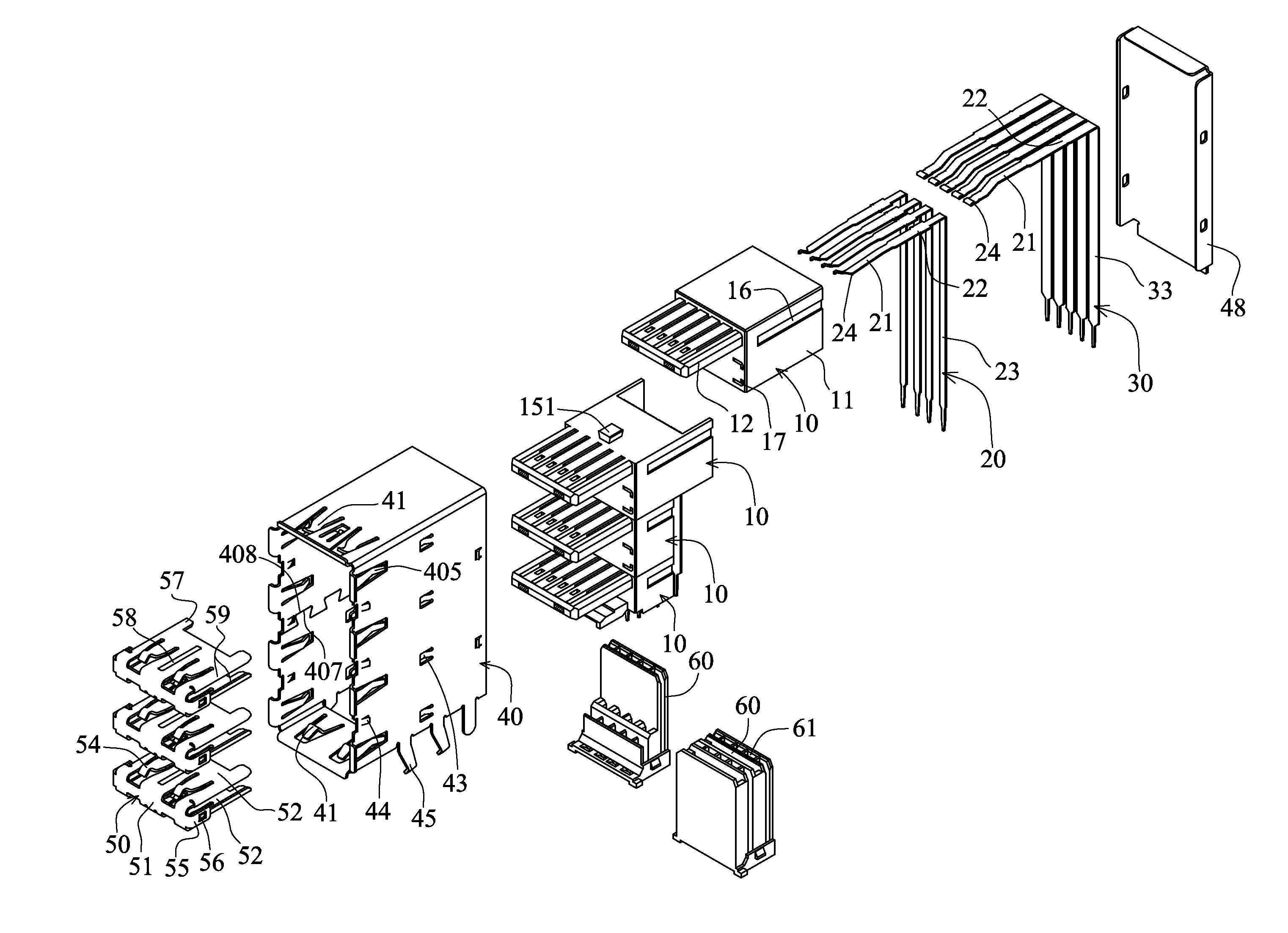
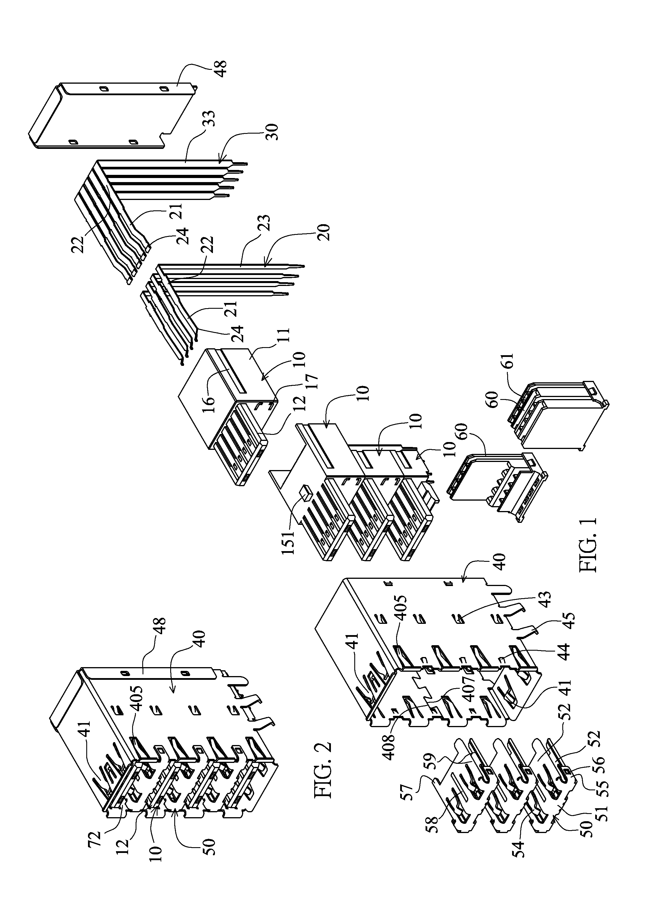
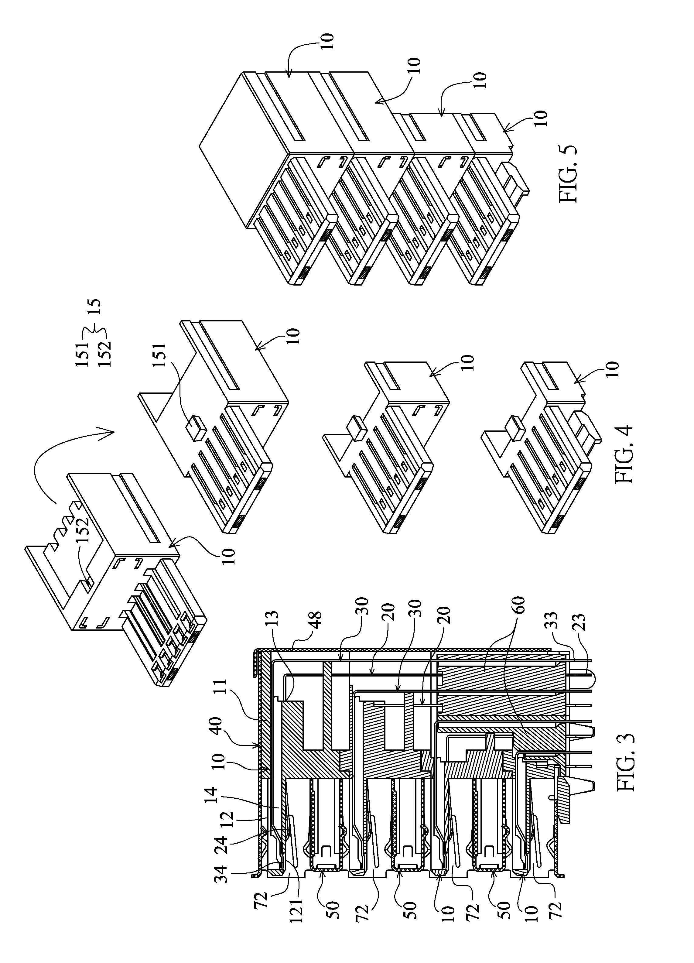
[0100]As shown in FIGS. 16 to 19, the invention is a vertical dual-layer HDMI socket including two insulating seats 10, a metal casing 40 and a separating member 50.
first embodiment
[0101]The two insulating seats 10 are formed by way of plastic injection molding. Each insulating seat 10 has a base 11, a tongue 12, one row of nine first terminal slots 13, one row of ten second terminal slots 14 and an engaging structure 15, and is substantially the same as the The top and bottom surfaces of the tongue 12 are jointing surfaces. The engaging structure 15 is disposed on or in the base 11 so that the two insulating seats 10 are stacked vertically. The engaging structure 15 includes the slot engaging with the engaging block. In addition, the front end of the base has a fitting structure 17 in the form of two slots.
[0102]Each insulating seat 10 has one row of nine first terminals 20 and one row of ten second terminals 30. The one row of first terminals 20 are assembled and fixed into the one row of first terminal slots 13. The one row of second terminals 30 is assembled and fixed into the one row of second terminal slots 14. The first terminal 20 integrally has an ex...
second embodiment
[0113]In addition, similar to the second embodiment, two sides of the two side plates of the separating member 50 are formed with vertical bent portions resting against and snapping to the inwardly projecting structure 42 of the metal casing 40 in the vertical direction, and hooking and restricting the hook portion 421 in the left-to-right direction.
[0114]As shown in FIG. 29, the eleventh embodiment of the invention is a lateral side standing single-layer USB 3.0 socket plus a single-layer HDMI socket plus a single-layer display port socket, and is substantially the same as the sixth and tenth embodiments except for the following differences. The three insulating seats 10″, 10, 10′ are directly stacked together. The metal casing 40 and the two separating members 50 form a USB 3.0 connection slot 72, a HDMI connection slot 65 and a display port connection slot 77. Each of front ends of two sides of the metal casing 40 is reversely bent toward the inside of the USB 3.0 connection slot...
PUM
 Abstract
Description
Claims
Application Information