System and method for detecting the ground and microphone input contacts in an audio plug

a microphone input and audio plug technology, applied in the direction of stereophonic circuit arrangement, two-part coupling device, coupling device connection, etc., can solve the problem that the signal transmitted from the accessory device cannot be interpreted properly by the mobile phone, the arrangement of these contact points on the audio plug is not standardized, and the number of stock keeping units (skus) of the accessory device is increased

Active Publication Date: 2014-01-16
STRIPE INC
View PDF2 Cites 97 Cited by
  • Summary
  • Abstract
  • Description
  • Claims
  • Application Information

AI Technical Summary

Benefits of technology

[0007]In general, in one aspect the invention provides a system comprising a mobile computing device, a peripheral device and a circuit. The mobile computing device includes an audio plug that has first and second contacts. The peripheral device includes an audio jack, and a microprocessor. The circuit connects the audio jack and the microprocessor and is used for detecting a microphone-in (MIC-IN) and a ground (GND) among the first and second contacts of the audio plug, wherein the MIC-IN has a higher voltage than the GND.
[0008]Implementations of this aspect of the invention may include one or more of the following features. The circuit includes a first comparator connected to a first switch and a second comparator connected to a second switch. The first comparator connects to the first and second contacts of the audio plug and measures a first voltage between the first and second contacts and the second comparator connects to the first and second contacts of the audio plug in a reverse way and measures a second voltage between the first and second contacts. The circuit further compares the first and second voltages between the first and second contacts and thereby identifies the MIC-IN and GND among the first and second contacts of the audio plug. The circuit further includes a resistor connected between first and second inputs of the first comparator and the first and second inputs of the first comparator are connected to the first and second contacts of the audio plug and the resistor is used to establish the first voltage between the first and second inputs of the first comparator and the first and second contacts of the audio plug. The resistor is further connected between first and second inputs of the second comparator and the first and second inputs of the second comparator are connected to the second and first contacts of the audio plug and the resistor is used to establish the second voltage between the first and second inputs of the second comparator and the second and first contacts of the audio plug. If the first voltage is low and the second voltage is high, the circuit turns the first switch on and the second switch off. If the first voltage is high and the second voltage is low, the circuit turns the second switch on and the first switch off. The first and second comparators comprise operational amplifiers. The first and second switches comprise N-MOS transistors. The circuit includes a comparator connected to a first switch and an inverter receiving input from the comparator and being connected to a second switch. The first comparator connects to the first and second contacts of the audio plug and measures a first voltage between the first and second contacts and the inverter receives the first voltage from the comparator and reverses the sign of the first voltage thereby generating a second voltage and the circuit further compares the first and second voltages and thereby identifies the MIC-IN and GND among the first and second contacts of the audio plug. If the first voltage is high and the second voltage is low, the circuit turns the first switch on and the second switch off. If the first voltage is low and the second voltage is high, the circuit turns the second switch on and the first switch off The circuit includes a first switch and a second switch and each of the first and second switches comprises N-MOS transistors. The first switch connects to the first and second contacts of the audio plug and the second switch connects to the first and second contacts of the audio plug in a reverse way. The audio jack connector comprises a ground (GND) contact, a microphone-in (MIC-IN) contact and one or more earphone channel contacts. The audio jack may be a 4-contact Tip-Ring-Ring-Sleeve (TRRS) connector, 3-contact Tip-Ring-Sleeve (TRS) connector, a 3.5 mm audio jack, a 6.35 mm audio jack, a 2.5 mm audio jack, RCA connector, XLR connector, a banana connector, mono or stereo versions thereof. The audio plug further includes one or more earphone channel contacts configured to connect to the audio jack one or more earphone channel contacts, respectively. The mobile computing device may be a mobile phone, a personal digital assistant (PDA), netbook, tablet computer, notebook computer, game console, e-book reader, portable video player, or digital audio player. The peripheral device may be a payment card reader, magnetic card reader, a printer, headphones, speakers, microphones, or hands-free versions thereof.
[0009]In general, in one aspect the invention provides a method for detecting a microphone-in (MIC-IN) and a ground (GND) in a mobile computing device. The method includes providing a mobile computing device comprising an audio plug. The audio plug comprises first and second contacts. Next, providing a peripheral device comprising an audio jack, and a microprocessor, and then providing a circuit connecting the audio jack and the microprocessor and used for detecting a microphone-in (MIC-IN) and a ground (GND) among the first and second contacts of the audio plug, wherein the MIC-IN has a higher voltage than the GND.

Problems solved by technology

Otherwise, signals transmitted from the accessory device cannot be interpreted properly by the mobile phone.
However, the arrangement of these contact points on an audio plug is not standardized yet.
This is not desirable for the merchants, because it increases the number of Stock Keeping Units (SKU) of an accessory device.
This is also not desirable for the consumers, because it makes it difficult to identify and choose a suitable accessory device for their mobile phones.

Method used


Image

  • System and method for detecting the ground and microphone input contacts in an audio plug
  • System and method for detecting the ground and microphone input contacts in an audio plug
  • System and method for detecting the ground and microphone input contacts in an audio plug

Examples


Embodiment Construction

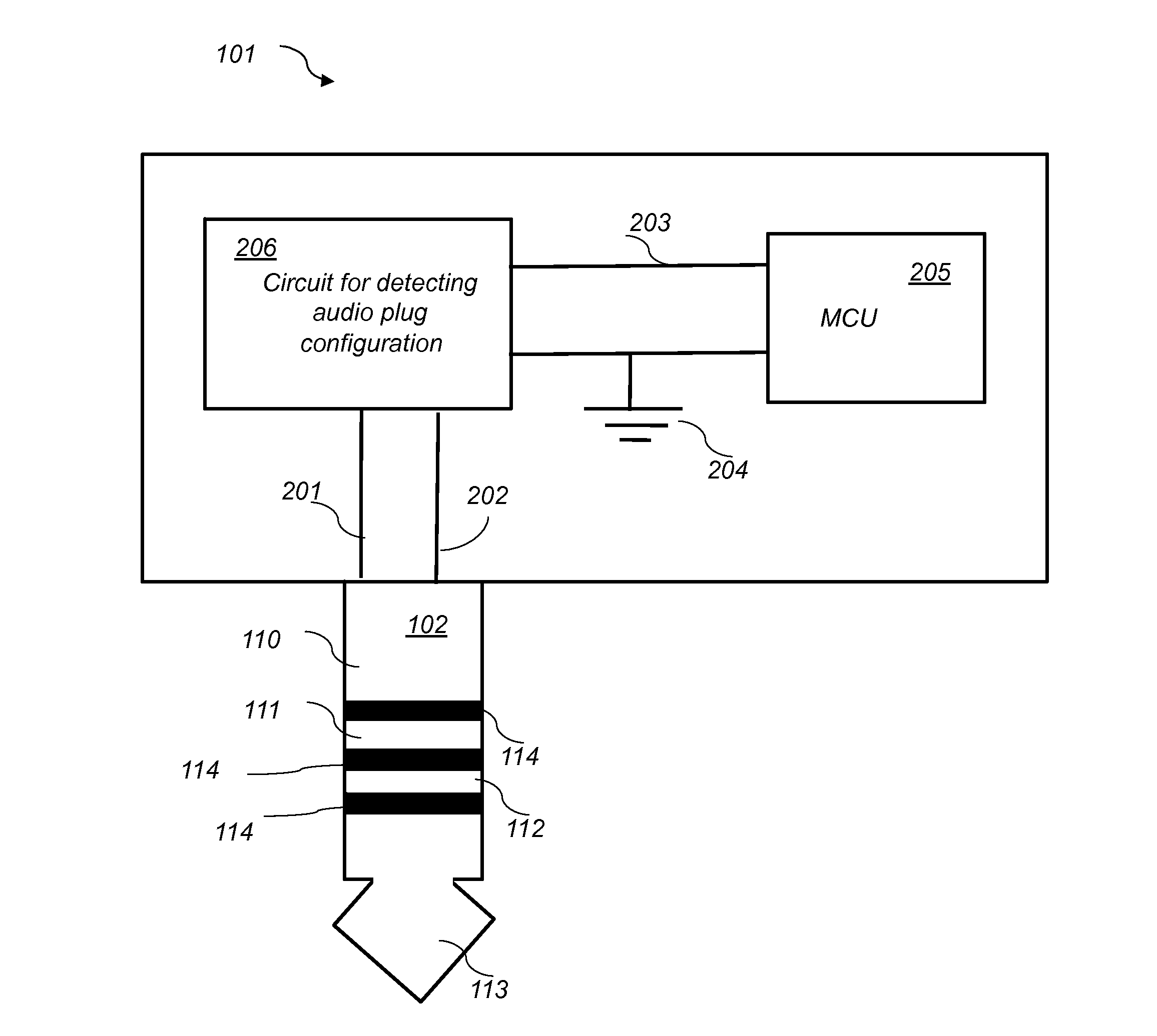
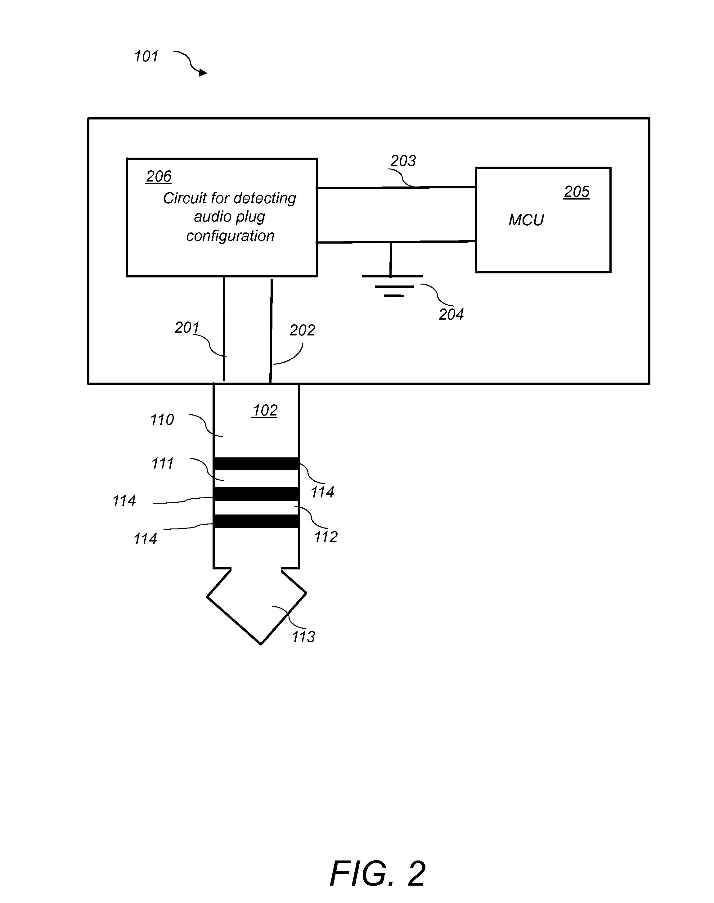
[0015]The present invention provides a circuit for detecting the position of the signal MIC-IN and GND on the audio plug of a mobile phone. The circuit includes two comparators and two switches. The comparators compare the voltage difference between the two contact points representing MIC-IN and GND of the audio plug of a mobile phone, and through this comparison the ground signal of the mobile phone is identified. The circuit then connects the ground of the accessory and the mobile phone properly, by activating the appropriate switch. The invention enables one single design of an accessory to be compatible to two different configurations of the audio plug on mobile phones.

[0016]The invention applies also to 3-pole arrangement where there is only a MONO audio signal instead of two stereo left and right audio channels (L-CH, R-CH). The invention may also be applied to other possible jack and plug configurations with MIC-IN and GND signals.

[0017]The invention applies to all different ...


PUM


Abstract

A circuit for detecting the position of the signal MIC-IN and GND on the audio plug of a mobile phone includes two comparators and two switches. The comparators compare the voltage difference between the two contact points representing MIC-IN and GND of the audio plug of a mobile phone, and through this comparison the ground signal of the mobile phone is identified. The circuit then connects the ground of the accessory and the mobile phone properly, by activating the appropriate switch.

Description

CROSS REFERENCE TO RELATED CO-PENDING APPLICATIONS[0001]This application claims the benefit of U.S. provisional application Ser. No. 61 / 671,119 filed on Jul. 13, 2012 and entitled SYSTEM AND METHOD FOR DETECTING THE GROUND AND MICROPHONE INPUT CONTACTS IN AN AUDIO PLUG, which is commonly assigned, and the contents of which are expressly incorporated herein by reference.FIELD OF THE INVENTION[0002]The present invention relates to a system and a method for detecting the ground and microphone input contacts in an audio plug of a mobile communication device.BACKGROUND OF THE INVENTION[0003]Portable personal computing devices such as smart phones, Personal Digital Assistant (PDA), portable computers, tablet computers and audio devices such as digital music players have become ubiquitous in recent years. These devices usually have different built-in physical electrical interfaces such as USB, FireWire, RS232 serial port and audio plug, among others. In almost all of these devices, and in ...

Claims


Application Information

Patent Timeline
Patent Type & Authority Applications(United States)
IPC IPC(8): H01R13/703
CPCH01R13/703H01R24/58H01R2107/00H04R5/04H04R2420/09H04R2420/05
Inventor LO, CHI WAHTSAI, HWAI SIANTSANG, KA LEONG TONY
Owner STRIPE INC
Why Eureka
Try Eureka