Lamina implant and method

a technology of lamina implants and implants, applied in the field of lamina replacement, can solve the problems of reducing the usefulness of spinal surgery, creating an unnatural state of the neck, and high risk of adjacent level segment instability,

Active Publication Date: 2014-01-16
GLOBUS MEDICAL INC
View PDF5 Cites 28 Cited by
  • Summary
  • Abstract
  • Description
  • Claims
  • Application Information

AI Technical Summary

Benefits of technology

[0010]The present invention is directed towards a prosthetic implant for restoring lamina after a laminectomy. The implant is generally a lamina-sized construct having a hollow interior. The lamina removed during the laminectomy may be converted to autologous bone that may then be placed inside the hollow interior of the implant. The implant is then secured to the remaining portion of the spine at the site of the laminectomy. An attaching agent, such as one or more plates with screws, may be used to secure the implant to the spine. Over time, the autologous bone inside the hollow interior of the implant will solidify as bone grows through the interior of the implant.

Problems solved by technology

Cervical fusion creates an unnatural state for the neck, however, as the entire fused neck segment is non-mobile.
There is a high risk of adjacent level segment instability after cervical fusion since all of the force with motion is transferred to the segment above and below the fusion.
Cervical laminoplasty has been devised for decompression and reconstruction of the cervical lamina, but has certain limitations that have decreased its usefulness in spinal surgery.
The primary issue is the technical difficulty of cervical laminoplasty.
This is a technically challenging technique.
As a large laminectomy defect is created, however, spinal instability can occur.
However, hemilaminotomies are technically difficult, time consuming, and cannot adequately decompress the bilateral nerve roots and central dura.
Lumbar fusions are routinely performed after lumbar laminectomies, but represent a plethora of technical difficulties and predispose the patient to “adjacent level” instability as forces are displaced above or below the fusion.
Misplacement of the screws has resulted in cerebrospinal fluid (CSF) leaks, nerve injury, and paralysis.

Method used


Image

  • Lamina implant and method
  • Lamina implant and method
  • Lamina implant and method

Examples


Embodiment Construction

[0017]The detailed description set forth below in connection with the appended drawings is intended as a description of presently-preferred embodiments of the invention and is not intended to represent the only forms in which the present invention may be constructed and / or utilized. The description sets forth the functions and the sequence of steps for constructing and operating the invention in connection with the illustrated embodiments. It is to be understood, however, that the same or equivalent functions, features, and sequences may be accomplished by different embodiments that are also intended to be encompassed within the spirit and scope of the invention.

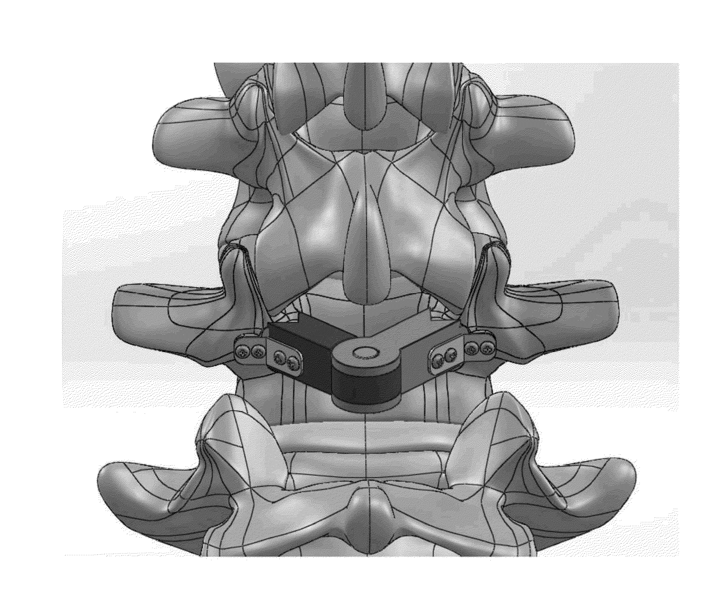
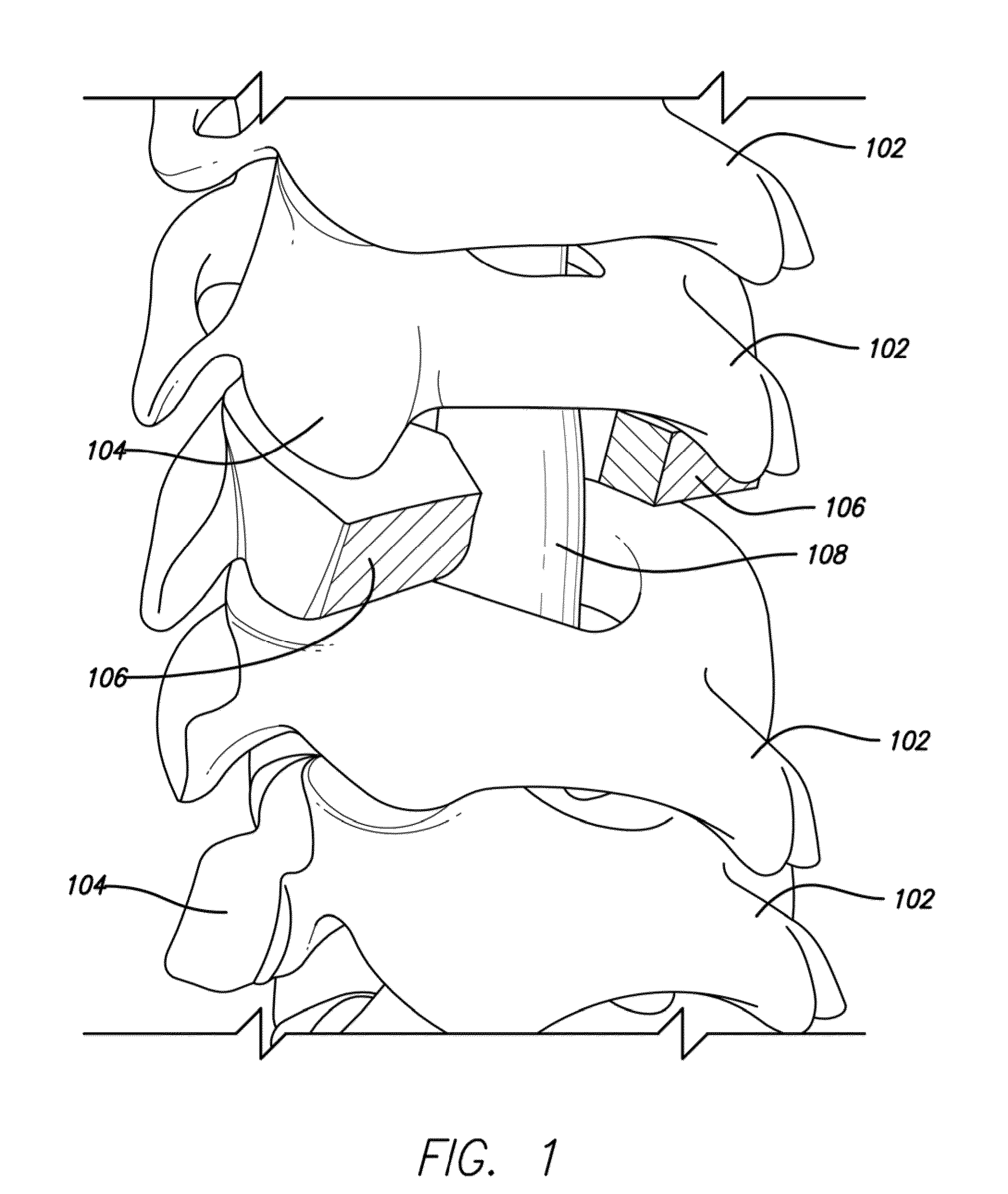
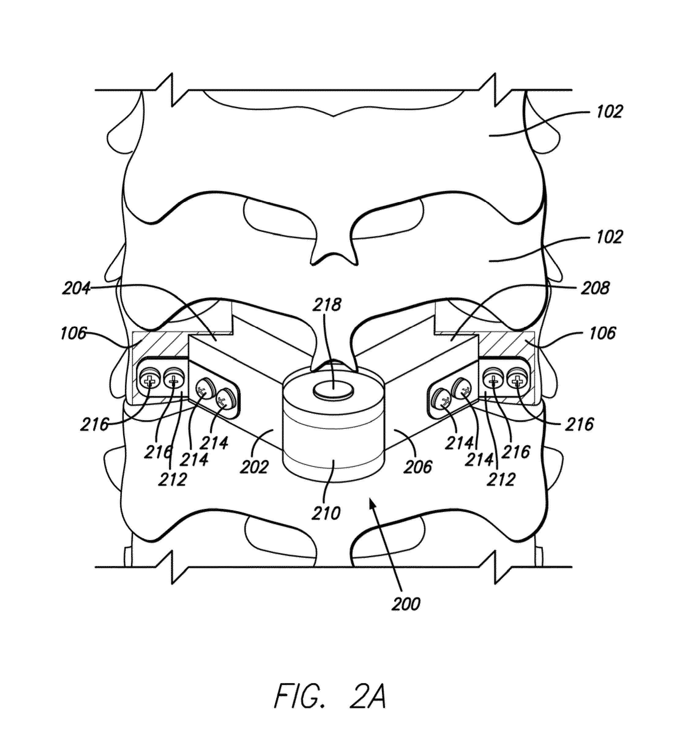
[0018]The present invention represents a novel implant and technique for the restoration of the lamina after cervical decompression or lumbar decompression. As seen in FIG. 1, when a surgeon performs a cervical or lumbar laminectomy by removing the lamina 102 of a spine 100, a gap is formed. In one embodiment of the present ...


PUM


Abstract

A prosthetic implant for restoring lamina after a laminectomy. The implant is generally a lamina-sized construct having a hollow interior. The lamina removed during the laminectomy may be converted to autologous bone that may then be placed inside the hollow interior of the implant. The implant may then be secured to the spine at the site of the laminectomy so that lamina restoration can occur as the hollow interior of the implant solidifies with bone growth.

Description

CROSS-REFERENCES TO RELATED APPLICATIONS[0001]This patent application claims the benefit of U.S. Provisional Patent Application Ser. No. 61 / 670,581 filed Jul. 11, 2012, which application is incorporated herein by this reference thereto.BACKGROUND OF THE INVENTION[0002]1. Field of the Invention[0003]This invention relates to the field of lamina replacement.[0004]2. Description of the Related Art[0005]Laminectomies, removal of the spinal lamina, are the most common surgical procedures in spinal surgery. Laminectomies are routinely performed in the cervical and lumbar spine to allow decompression of key areas of the spine.[0006]Cervical laminectomies allow decompression of the spinal cord and nerve roots. Patients may present with a radiculopathy (pain in the arms), myelopathy (weakness in arms and legs), or a combination of both. Cervical laminectomies are performed over multiple cervical levels and are an effective technique for cervical decompression and relief of symptoms. Removal ...

Claims


Application Information

Patent Timeline
Patent Type & Authority Applications(United States)
IPC IPC(8): A61F2/44
CPCA61F2/44A61B17/7071A61F2002/2835A61F2002/30471A61F2002/30476A61F2002/30538A61F2002/30578A61F2002/30593A61B17/707
Inventor MOUW, GRAHAM J.
Owner GLOBUS MEDICAL INC
Why Eureka
Try Eureka