Active mechanical force sensor

a sensor and active technology, applied in the field of contactless force measurement sensor, can solve problems such as difficulty in pre-processing

Active Publication Date: 2014-01-23
ABAS
View PDF14 Cites 5 Cited by
  • Summary
  • Abstract
  • Description
  • Claims
  • Application Information

AI Technical Summary

Benefits of technology

[0012]The features of the contactless force measurement sensor as described above and hereinafter may be the follows: non-contact or contactless sensing principle; using magnetic principles for force measurement; being insensitive or substantially insensitive to magnetic fields that are already present or stored in the object to be sensed; no necessity for treating the object to be sensed in whatever way; no degradation of the sensor performance over time as it is an active sensing principle; measuring in differential mode; sensitivity to a single axis bending force may be realized (no cross talk between bending forces in different directions); may works on objects to be sensed that are static or that rotate at any speed; insensitivity to light, dust, mechanical shocks, water, humidity, oil, for example; works with any object containing metallic material as long as it attracts a magnet and conducts magnetic flux lines; may tolerate an air gap or spacing between the object to be sensed and the contactless force measurement sensor; may be applied to objects with varying dimensions (shaft diameter, for example); the temperature operating range may be from −50° C. to more than 210° C.
[0013]Active magnetic principle mechanical force sensor means that there will be no need for a “permanent” magnetization of the object to be sensed to make the sensor work. An active mechanical force sensor can function immediately after placing the sensor hardware appropriately close to the test object or object to be sensed.

Problems solved by technology

Mounting elements to a shaft may influence the movement of the shaft, pre-processing may be difficult when the shaft is not accessible or cannot be dismounted for pre-processing.

Method used


Image

  • Active mechanical force sensor
  • Active mechanical force sensor
  • Active mechanical force sensor

Examples


Embodiment Construction

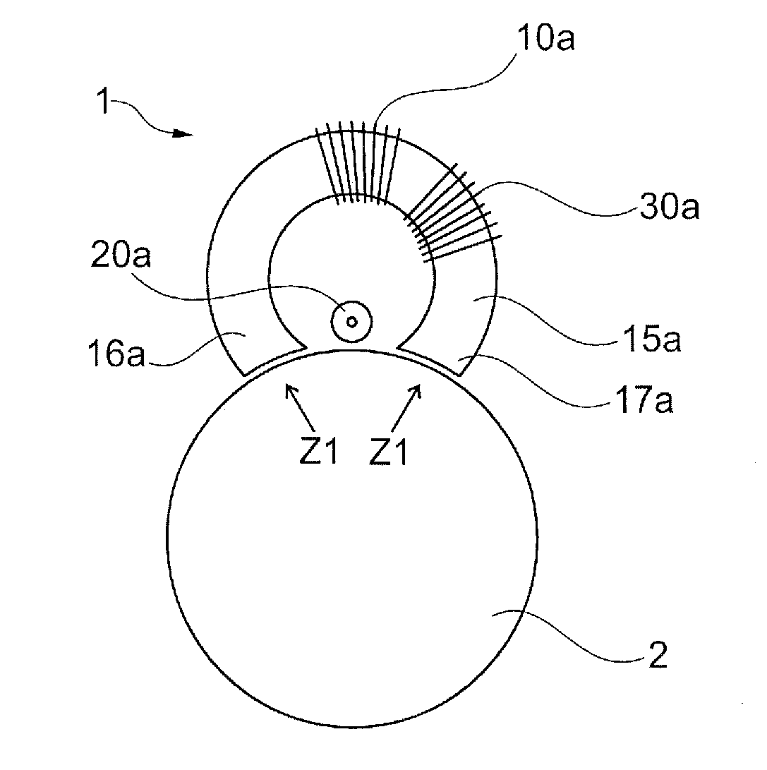
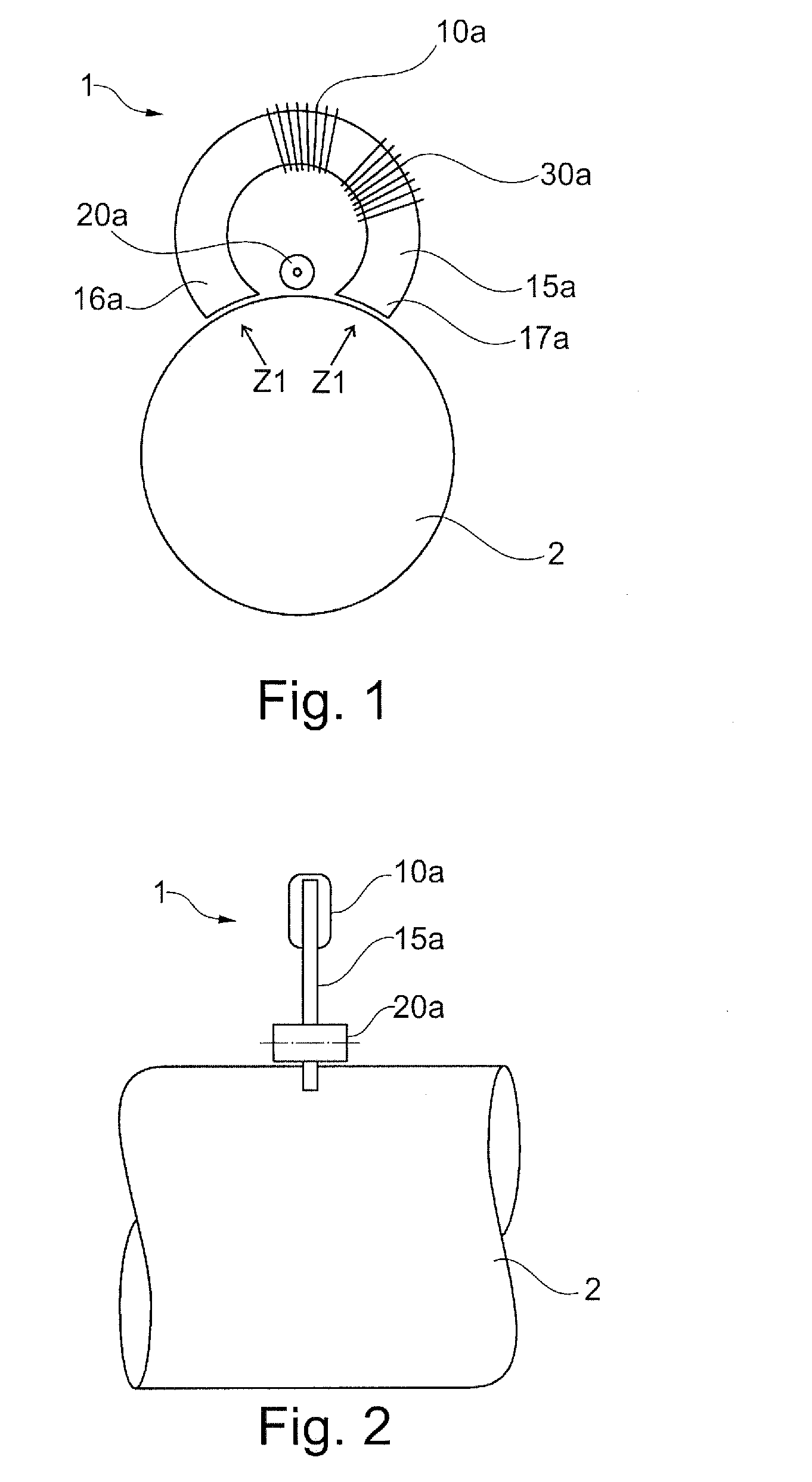
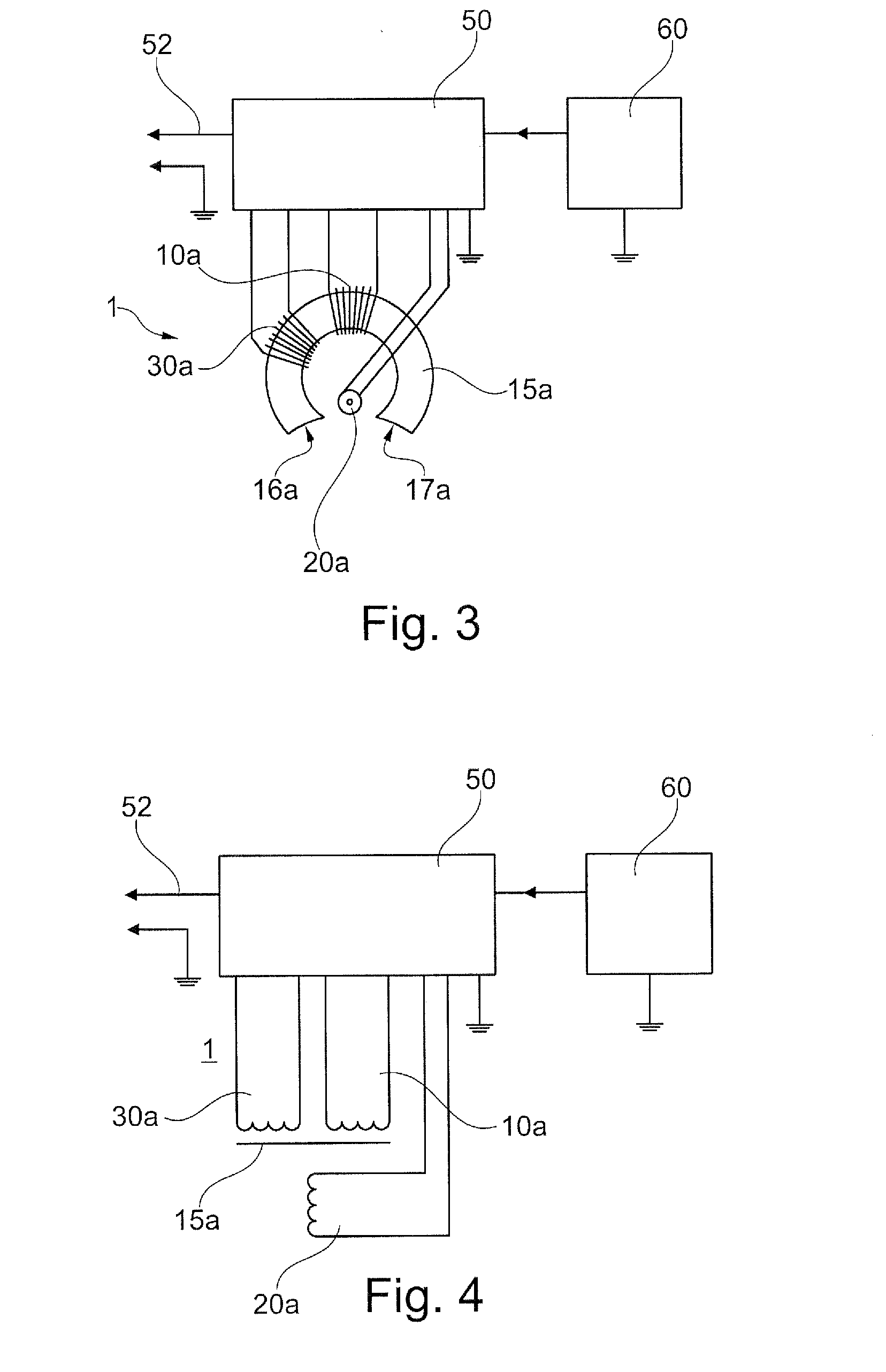
[0116]FIG. 1 illustrates a contactless force measurement sensor 1 and a circular object to be sensed 2. The contactless force measurement sensor 1 comprises a flux concentrator 15a with a first magnetic field generating unit 10a and a feedback element 30a attached to the flux concentrator. The flux concentrator comprises a first pole 16a and a second pole 17a, wherein the first pole and the second pole are directed along the first facing orientation z1 towards a surface of the object to be sensed.

[0117]The flux concentrator is shaped in form of a C-shape or U-shape, and in particular in form of an arc of a circle. The surface of the first pole and of the second pole may be adapted to the surface of the object to be sensed, i.e. the surface of the poles is also circular shaped and in particular concave.

[0118]The first magnetic field generating unit 10a is driven with an alternating current and generates a magnetic field whose magnetic field lines are concentrated and directed towards...


PUM

PropertyMeasurementUnit
temperatureaaaaaaaaaa
angleaaaaaaaaaa

Abstract

A contactless force measurement sensor for measuring an applied force onto an object is provided. The contactless force measurement sensor includes a first facing orientation which facing orientation defines an orientation pointing towards a surface of the object, a first magnetic field generating unit being adapted for generating a magnetic field towards the facing orientation, a first magnetic field detector unit being adapted for detecting a first magnetic field which field being generated by the first magnetic field generating unit and being influenced by an applied force to be measured, wherein the first magnetic field detector unit is further adapted for outputting a first signal being representative for the detected magnetic field, and an evaluating unit being adapted for evaluating a signal strength of the first signal and determining the applied force based on the first signal.

Description

FIELD OF THE INVENTION[0001]The present invention relates to a contactless force measurement sensor and to a sensing arrangement having such a contactless force measurement sensor for measuring an applied force onto an object.TECHNICAL BACKGROUND[0002]Force measurement is important for many industrial applications, in particular for arrangements being dynamically impacted by a force. Applied forces may be pressuring forces as well as moments like torque and bending impact. An exemplary application for torque is a shaft for a vehicle being arranged between a motor and e.g. a wheel. For determining a torque in the shaft, either a particular element may need to be mounted to the shaft, or the shaft may need to be pre-processed, e.g. magnetized. Mounting elements to a shaft may influence the movement of the shaft, pre-processing may be difficult when the shaft is not accessible or cannot be dismounted for pre-processing.[0003]In industry applications and laboratory research and developm...

Claims


Application Information

Patent Timeline
Patent Type & Authority Applications(United States)
IPC IPC(8): G01L1/12
CPCG01L1/12G01L1/127G01L1/125
Inventor MAY, LUTZ
Owner ABAS
Why Eureka
Try Eureka