
Low-voltage circuit breaker and power measuring arrangement

a low-voltage circuit breaker and power measurement technology, applied in the direction of power measurement by current/voltage, emergency protective circuit arrangement, instruments, etc., can solve the problem of rogowski coils, resultant (residual) phase error in relation to original signal, and inability to determine the phase accuracy of the ascertained current level

Pending Publication Date: 2022-08-25
SIEMENS AG
View PDF5 Cites 0 Cited by
  • Summary
  • Abstract
  • Description
  • Claims
  • Application Information

AI Technical Summary

Benefits of technology

The invention describes a method to compensate for phase errors in a current signal by using a voltage signal. This is done by interpolating voltage values that are present only in discrete time intervals and correlating them with the current values. This helps to avoid or minimize errors in power value calculations. The method is simple and inexpensive and can be easily adapted. It also allows for direct use of the ascertained phase error of the current as a phase difference to interpolate the voltage value. Additionally, the method avoids compensating for different sampling rates and thus different time intervals and provides a comparison that is performed upon putting into service, eliminating the need for further comparison for a first accuracy requirement.

Problems solved by technology

Rogowski coils have the disadvantage that the ascertained level of the current is not accurate in terms of phase.
Following the signal derivation by the Rogowski transformer and the subsequent integration by an analog integrator, there is a resultant (residual) phase error in relation to the original signal (current to be ascertained in the conductor).

Method used


Image

  • Low-voltage circuit breaker and power measuring arrangement
  • Low-voltage circuit breaker and power measuring arrangement

Examples


Embodiment Construction

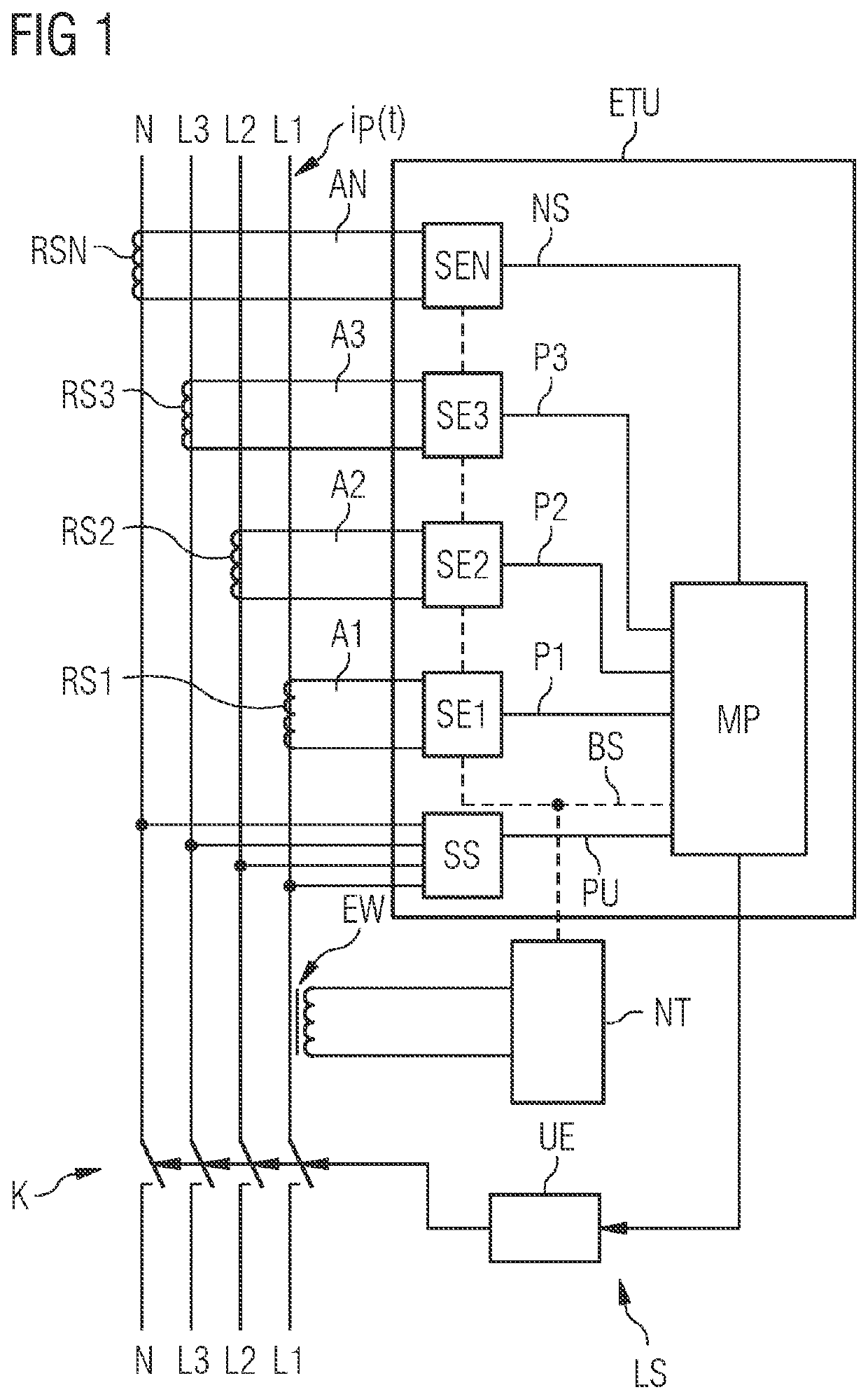
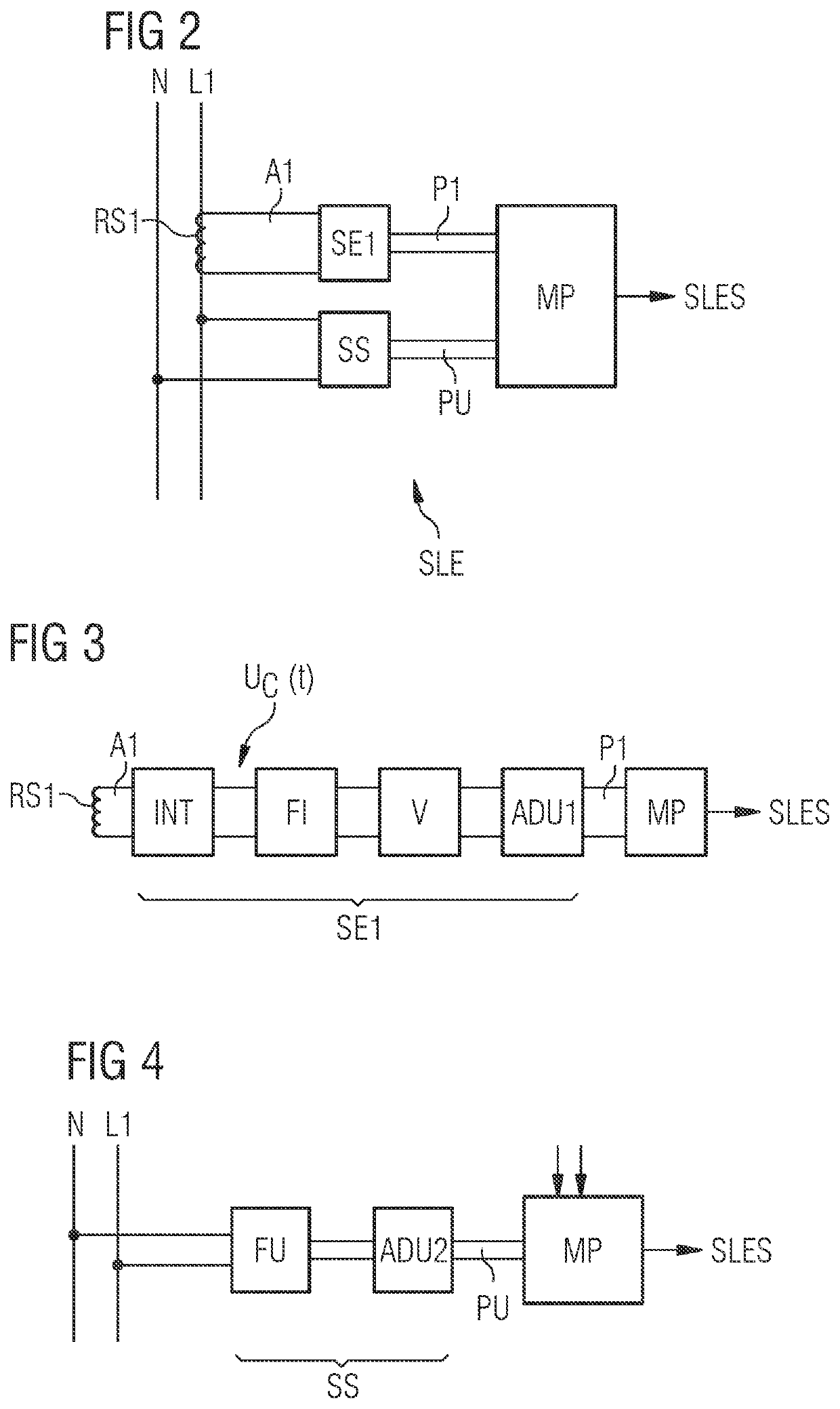
[0067]Referring now to the figures of the drawing in detail and first, in particular, to FIG. 1 thereof, there is shown a schematic block diagram of a low-voltage circuit breaker LS. FIG. 1 shows electrical conductors L1, L2, L3, N of a low-voltage circuit, for example a three-phase AC circuit, wherein the first conductor L1 forms the first phase with the first phase current ip(t), the second conductor L2 forms the second phase with the second phase current, the third conductor L3 forms the third phase with the third phase current and the fourth conductor forms the neutral conductor N with the neutral conductor current of the three-phase AC circuit.

[0068]In the example according to FIG. 1, the first conductor L1 is connected to an energy converter EW (for example as part of a set of converters) in such a way that at least a portion of the current, that is to say a partial conductor current, or the entire current of the first conductor L1 flows through a primary side of the energy co...


PUM


Abstract

A power value for a low-voltage AC circuit, such as low-voltage circuit breaker, is derived. A voltage between conductors of the low-voltage AC circuit is ascertained and a current of at least one conductor is ascertained by a Rogowski coil, which outputs an analog voltage that is an equivalent to the level of the electric current. The analog voltage of the Rogowski coil is integrated and then digitized, and the level of the voltage is digitized. A power value is calculated in each case from a sample value of the current and an interpolated voltage value. The interpolated voltage value is in each case ascertained from two successive sample values of the voltage such that a phase error generated by the Rogowski coil or / and the integrator is compensated for in relation to the electric current in the conductor and a phase error-free power value is ascertained.

Description

CROSS-REFERENCE TO RELATED APPLICATION[0001]This application claims the priority, under 35 U.S.C. § 119, of German Patent Application DE 10 2021 201 810.6, filed Feb. 25, 2021; the prior application is herewith incorporated by reference in its entirety.FIELD AND BACKGROUND OF THE INVENTION[0002]The invention relates to the technical field of a low-voltage circuit breaker for a low-voltage AC circuit, a power measuring arrangement for a low-voltage AC circuit, in particular for low-voltage circuit breakers, and a method for ascertaining a power for a low-voltage AC circuit, in particular for a low-voltage circuit breaker.[0003]Circuit breakers are protection devices, which function in a similar way to a fuse. Circuit breakers monitor the current flowing through them by way of a conductor and interrupt the electric current or flow of energy to an energy sink or a load, which is referred to as tripping, when protection parameters, such as current limit values or current / time period lim...

Claims


Application Information

Patent Timeline
IPC IPC(8): H02H3/08H02H1/00G01R15/18G01R19/165G01R21/06
CPCH02H3/08H02H1/0007G01R15/181G01R19/16571G01R21/06
Inventor KOPACZEWSKI, PETERBRUELL, MARCO
Owner SIEMENS AG
Learn More