
Active mechanical force and axial load sensor

a technology of axial load and active mechanical force, which is applied in the direction of magnetic property measurement, instruments, material magnetic variables, etc., can solve the problems of difficult pre-processing, and achieve the effects of reducing signal gain, increasing sensor system performance, and reducing the hysteresis of relative large measuremen

Active Publication Date: 2016-11-15
ABAS
View PDF7 Cites 3 Cited by
  • Summary
  • Abstract
  • Description
  • Claims
  • Application Information

AI Technical Summary

Benefits of technology

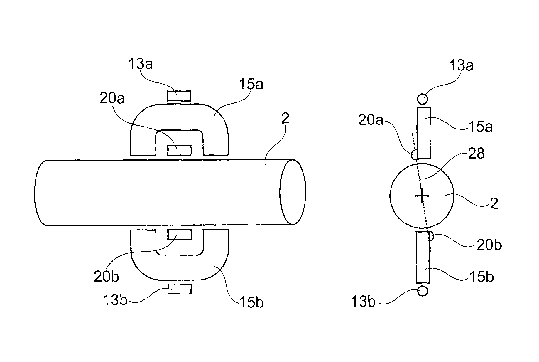
[0017]As the first magnetic field detector unit comprises a lateral offset with respect to the poles of the first flux concentrator, the sensitivity of the first magnetic field detector unit may be increased as an axial force may in particular influence or influence with an increased effect magnetic field lines being distant to a central axis of the flux concentrator. Thus, axial forces applied to a longitudinal object may be detected with higher accuracy.
[0040]The first sensing unit and the second sensing unit may be used for providing measurement redundancy and avoiding or minimizing errors in measurement.
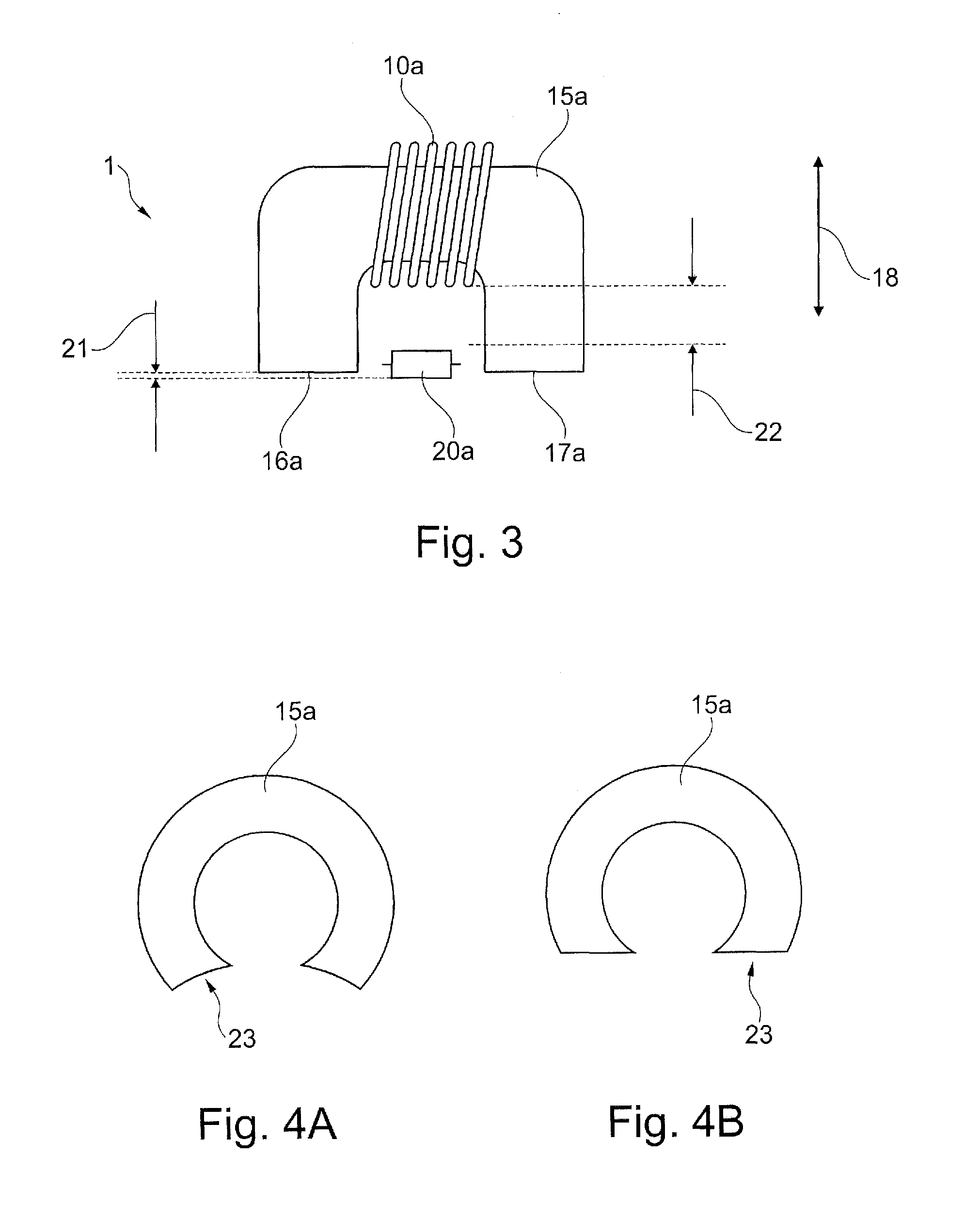
[0060]As the coil is arranged in between the first pole and the second pole, the coil may optimally detect the changed magnetic conductivity which leads to a changed magnetic field strength between the poles, as the magnetic field may be distracted by the object to be sensed in case the object to be sensed is subjected to a mechanical force.
[0066]The sensor system as described above and hereinafter may be sensitive to external magnetic stray fields, when hitting the same frequency as the operational frequency of this sensor. There are several solutions applicable to eliminate the unwanted effects caused by interfering signals: magnetic shielding, adding one more level of differential mode magnetic field sensing devices (which will compensate for the effects of EMI), or frequency hopping of the sensor system.
[0073]When using hardened shaft material (in comparison to unhardened test object material) the potentially relative large measurement hysteresis may become smaller, and eventually will disappear to a non detectable level. In many cases, hardening the test object material (at least at the sensing location) may also reduce the signal gain. However, the gained signal quality (low hysteresis, high linearity) may make this worthwhile.

Problems solved by technology

Mounting elements to a shaft may influence the movement of the shaft, pre-processing may be difficult when the shaft is not accessible or cannot be dismounted for pre-processing.

Method used


Image

  • Active mechanical force and axial load sensor
  • Active mechanical force and axial load sensor
  • Active mechanical force and axial load sensor

Examples


Embodiment Construction

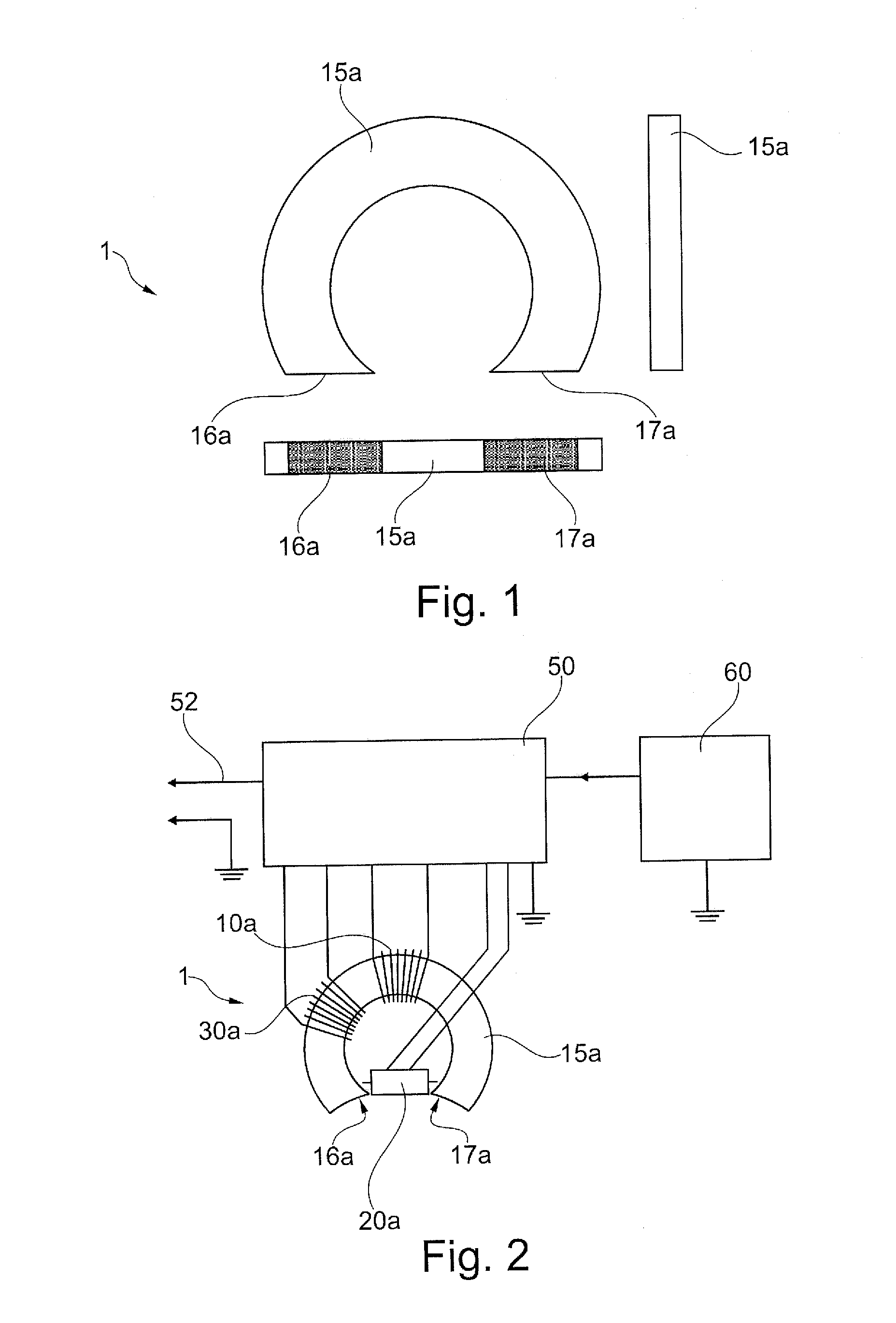
[0100]FIG. 1 illustrates a three-side view of a first flux concentrator 15a of a force measurement sensor 1. The first flux concentrator 15a has a first pole 16a and a second pole17a. The surfaces of both poles 16a, 17a are pointing in the same direction, i.e. in the first facing direction.

[0101]As will be described in more detail below, the surfaces may be arranged within the same plane or may be parallel to each other. In an alternative embodiment, the surfaces of the poles may be inclined to each other.

[0102]The flux concentrator is shaped in form of a C-shape or U-shape, and in particular in form of an arc of a circle. The surface of the first pole and of the second pole may be adapted to the surface of the object to be sensed, i.e. the surface of the poles is also circular shaped and in particular concave.

[0103]The first flux concentrator with the generator coil wound around it has the task to produce and to maintain a controlled and active magnetic field path beneath the surfa...


PUM

PropertyMeasurementUnit
angleaaaaaaaaaa
angleaaaaaaaaaa
angleaaaaaaaaaa

Abstract

A force measurement sensor for measuring an applied force onto an object is provided. The force measurement sensor includes a sensing unit including a concentrator, a generator, a detector, and an evaluator. The concentrator points towards the object. The generator generates a magnetic field. The detector detects a magnetic field generated by the generator and influenced by the applied force to be measured. The detector outputs a first signal of the detected magnetic field. The evaluator evaluates a signal strength of the signal and determines the applied force based on the signal. A longitudinal axis of the detector is arranged for a lateral offset between the longitudinal axis of the detector and a central axis of the concentrator that is perpendicular to a longitudinal direction of the concentrator.

Description

FIELD OF THE INVENTION[0001]The present invention relates to a contactless force measurement sensor and to a sensing arrangement having such a contactless force measurement sensor for measuring an applied force onto an object, in particular an axial force applied to a longitudinal object.TECHNICAL BACKGROUND[0002]Force measurement is important for many industrial applications, in particular for arrangements being dynamically impacted by a force. Applied forces may be pressuring forces as well as moments like torque, bending impact, or forces in an axial direction of an object. An exemplary application for torque is a shaft for a vehicle being arranged between a motor and e.g. a wheel. For determining a force in the shaft, either a particular element may need to be mounted to the shaft, or the shaft may need to be pre-processed, e.g. magnetized. Mounting elements to a shaft may influence the movement of the shaft, pre-processing may be difficult when the shaft is not accessible or ca...

Claims


Application Information

Patent Timeline
Patent Type & Authority Patents(United States)
IPC IPC(8): G01B7/16G01N27/72G01D5/14G01L1/12G01L3/10G01L1/00
CPCG01N27/72G01D5/145G01L1/12G01L1/127G01L3/101
Inventor MAY, LUTZ
Owner ABAS
Learn More