Electronic percussion device and method

a technology of electronic percussion and percussion instruments, applied in the direction of measuring devices, electrophonic musical instruments, instruments, etc., can solve the problems of delay in sound reproduction in response to a trigger that cannot be noticed even by the trained ear of a musician, and the second portion is considered inferior, and the related art does not address this problem at all

Active Publication Date: 2014-01-23
SHEMESH GUY
View PDF30 Cites 35 Cited by
  • Summary
  • Abstract
  • Description
  • Claims
  • Application Information

AI Technical Summary

Benefits of technology

[0013]It is yet an object of the present invention to configure the peripheral carrier as a rigid hollow body made of solid material that extends from the drumhead bottom surface to the at least one sensor, and to dispose the peripheral carrier top edge sufficiently adjacent to the drum shell to avoid percussion strokes impinging directly thereover. The peripheral carrier is biased by the drumhead onto the at least one sensor which is disposed on the sensors support in a configuration allowing at least one degree of freedom of motion of the peripheral carrier, which vibrates and communicates vibration.

Problems solved by technology

It is well known that the second portion is considered inferior because the “feel” of playing while striking on rubber does not compare to the striking on a vibrating surfaces, since the drumstick barely bounces back from a rubber surface.
However there are several other issues that need be addressed when modeling behavior of acoustic drums.
First, the delay in sound reproduction in response to a trigger must go un-noticed even to the trained ear of a musician.
The related art does not address this problem at all, even though trained musicians actually recognize small delays while playing electronic percussion instruments.
Although this method will work in general, it is extremely susceptible to noises and to variances in stroke intensity that leads to only a rough estimate of stroke position.
First, the cost of producing such an instrument is significant since it is a complex device comprised of several layers and having a special controller board installed per each drum.
Second, the drumhead used is a rubber material so percussion feeling is not as good as a vibrating drumhead or mesh and third, there is no rim shot capability.
Another problem that has not been addressed in the related art is the lack of linearity in detection of stroke intensity or velocity as function of position.
It turns out that mounting a single sensor under the center of the drumhead, as disclosed by Yoshino and Susami has a problem when a direct stroke is applied in the center of the drum directly above the sensor's cushioning member.
Due to this fact there exists a circular area at the center of the drum, having a radius of about 1.5 cm in which sounds are output very loudly when compared to other areas on the drumhead, thereby adversely affecting the realism and feel of playing the instrument.

Method used


Image

  • Electronic percussion device and method
  • Electronic percussion device and method
  • Electronic percussion device and method

Examples


embodiment 1000

[0108]The description hereinbelow refers mainly to the structure of the embodiment 1000 even though the alternative embodiments are applicable and practical too.

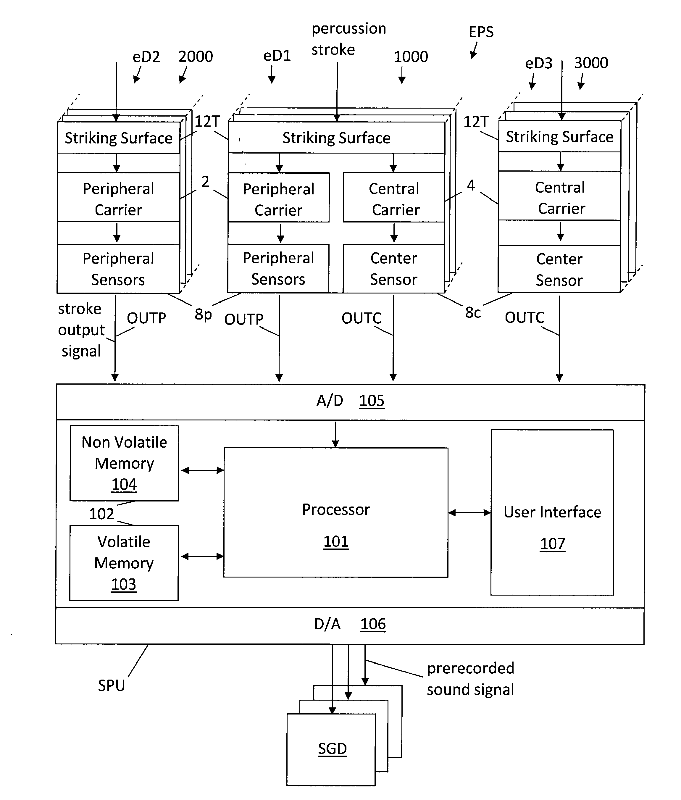
[0109]Reference is now made to FIG. 4, which illustrates a schematic representation of an exemplary electronic percussion system EPS which has a plurality of electronic percussion devices eD of various embodiments, such as for example the electronic percussion devices eD1, eD2 and eD3, and so on. However, the electronic percussion system EPS may also be operated with just one single electronic percussion device eD or with more than one electronic percussion device eD of the same or of different embodiment.

[0110]FIG. 4 shows three different embodiments of the present invention, namely the embodiment 1000 having at least one peripheral sensor 8p and a center sensor 8c, embodiment 2000 with only peripheral sensors 8p, and embodiment 3000 including only the center sensor 8c. The embodiments 1000, 2000, and 3000 are marked respec...

embodiment 3000

[0214]As described hereinabove and shown in steps S17-S24 in FIG. 13, should a new stroke output signal be detected, then the state of the primary channel would not be Idle. Furthermore, after the detection of a new percussion signal feature, it is also known whether the percussion stroke is a normal percussion stroke or a rim shot. If in step S44 the state of the primary channel is Idle, then the function returns, preserving the Idle state of the procedure step S14. However, if the state of the primary channel is not Idle, then control is passed to step S45 where the channel is checked for detection of a normal percussion stroke or of a rim shot. In the embodiments 1000 and 2000, the primary channel is defined to be the peripheral channel and therefore, the decision between a normal percussion stroke and a rim shot is made with excellent results. In the embodiment 3000, it is the central channel that is checked so that the decision is made with good results, although not as good as...

embodiment 2000

[0216]The process continues to step S49, which is called iteratively in a loop of the main audio process when the state is set to NormalSound, where each new iteration updates the sounds that are generated with a more accurate estimation. This is done until the transient period elapses for all the channels available with the current percussion device. For the embodiment 1000 and 3000, this occurs when the available channels exit the SearchMax state, at which point both maximum values of the sound signals are known, and the position and intensity results are accurate. For the embodiment 2000, the transient period elapses only after exiting the SearchMax and SearchMin state, as will be described hereinbelow.

[0217]As described hereinabove, the estimation process in step S49 was introduced in order to minimize the delay, knowing that it is much more important to output an inaccurate sound signal as quickly as possible and to care for an update later on, rather than to wait until all the...


PUM


Abstract

An electronic percussion device includes a drum shell, a drumhead as striking surface, vibration sensors, and a peripheral and a central vibration carrier. The vibration carriers abut against the drumhead to convey vibrations therefrom to the sensor(s). The central vibration carrier is a helicoidal spring. The peripheral vibration carrier is a rigid body of solid material supported by peripheral sensors disposed thereunder. Two electrical leads of each one of the peripheral sensors are correspondingly coupled in parallel to produce only two common output leads. An electronic sound module is configured to sample the sensors and employs software procedures to detect percussion strokes delivered on the drumhead, and to generate sounds accordingly. The software procedures use averaged and aggregated signals to provide accurate detection of position and intensity of a drum stroke. Alternative embodiments of the device use only a peripheral vibration carrier or only a central vibration carrier.

Description

[0001]This is a Divisional of U.S. application Ser. No. 12 / 987,256, filed Jan. 10, 2011, the entire contents of which are incorporated herein by reference.TECHNICAL FIELD[0002]The present invention relates to electronic percussion instruments, such as drums and cymbals, and in particular, to electronic percussion devices able to detect the position and the intensity of a stroke, either on the drumhead or on the drum rim, and output prerecorded sounds in accordance with the detected stroke position and intensity.RELATED ART[0003]The related art may roughly be categorized into two portions, namely a first portion regarding inventions that involve a striking surface able to vibrate, such a mesh head, and a second portion where the striking surface is made of rubber. It is well known that the second portion is considered inferior because the “feel” of playing while striking on rubber does not compare to the striking on a vibrating surfaces, since the drumstick barely bounces back from a...

Claims


Application Information

Patent Timeline
Patent Type & Authority Applications(United States)
IPC IPC(8): G10H7/00
CPCG10H7/00G10H3/146G10H2220/525G10H2230/275
Inventor SHEMESH, GUY
Owner SHEMESH GUY
Why Eureka
Try Eureka