Garlic Press

a technology of garlic press and rotary press, which is applied in the field of garlic press, can solve the problems of affecting the convenience of use, and affecting the functionality of integrated design, etc., and achieves the effect of convenient us

Inactive Publication Date: 2014-01-23
LEE TUNG HSIEN
View PDF10 Cites 8 Cited by
  • Summary
  • Abstract
  • Description
  • Claims
  • Application Information

AI Technical Summary

Benefits of technology

[0004]It is an objective of the present invention to provide a garlic press for improving the above mentioned problems. The pivotal point of the garlic press is disposed close to a middle portion of the ...

Problems solved by technology

Therefore, the convenience of using the garlic press A1 is substantially limited.
More specifically, an angle for operating the garlic press A1 during usage and the angle of opening are comparatively larger, which will affect the con...

Method used


Image

  • Garlic Press
  • Garlic Press
  • Garlic Press

Examples


first embodiment

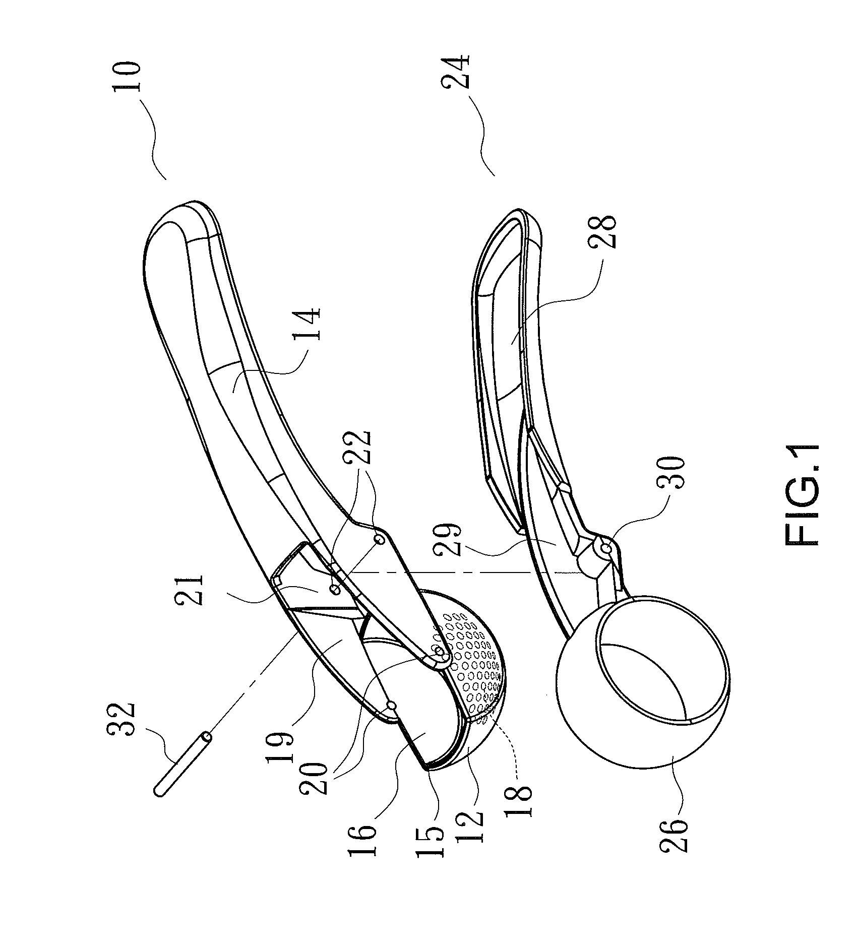
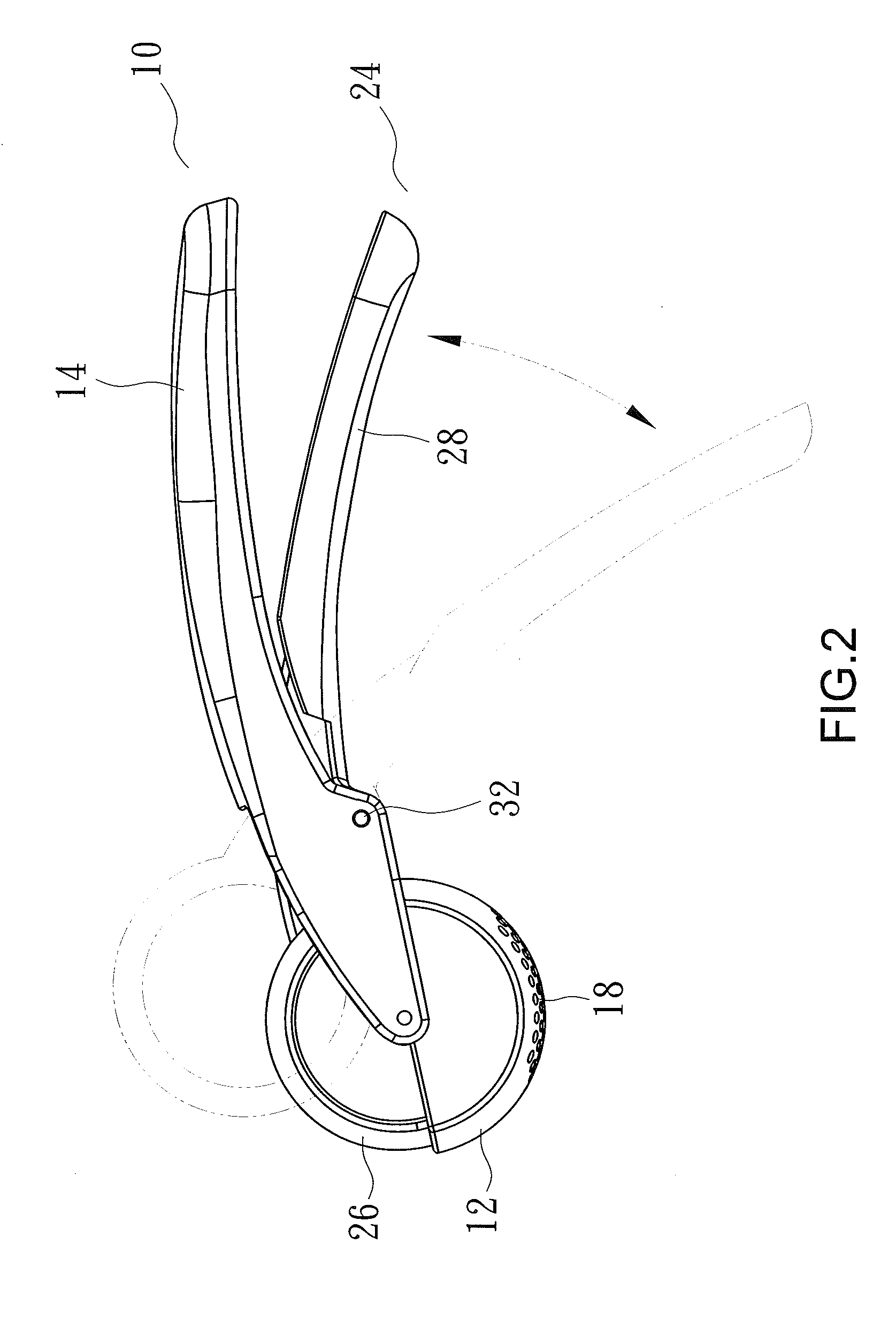
[0022]A garlic press according to the present invention is shown in FIGS. 1 and 2 of the drawings and includes a grip member 10 and a crush member 24. The grip member 10 includes a housing body 12 and an upper handle 14 extending backward from an upper end of the housing body 12. An opening 15 is formed in the upper end of the housing body 12, and a chamber 16 is disposed inside the housing body 12 for accommodating to-be-crushed garlic clove or garlic bulblet (not shown). A plurality of holes 18 is disposed in a bottom of the housing body 12 to prevent the chamber 16 from becoming a complete closed space during crushing of garlic. The holes 18 can reduce the resistance during crushing, and a portion of garlic juice produced from crushing garlic can be discharged through the holes 18 to reduce the acting force required from crushing. Two spaced lateral walls 19 are formed on a front end of the upper handle 14 and define a pivotal space 21 between the two lateral walls 19. Two oppose...

second embodiment

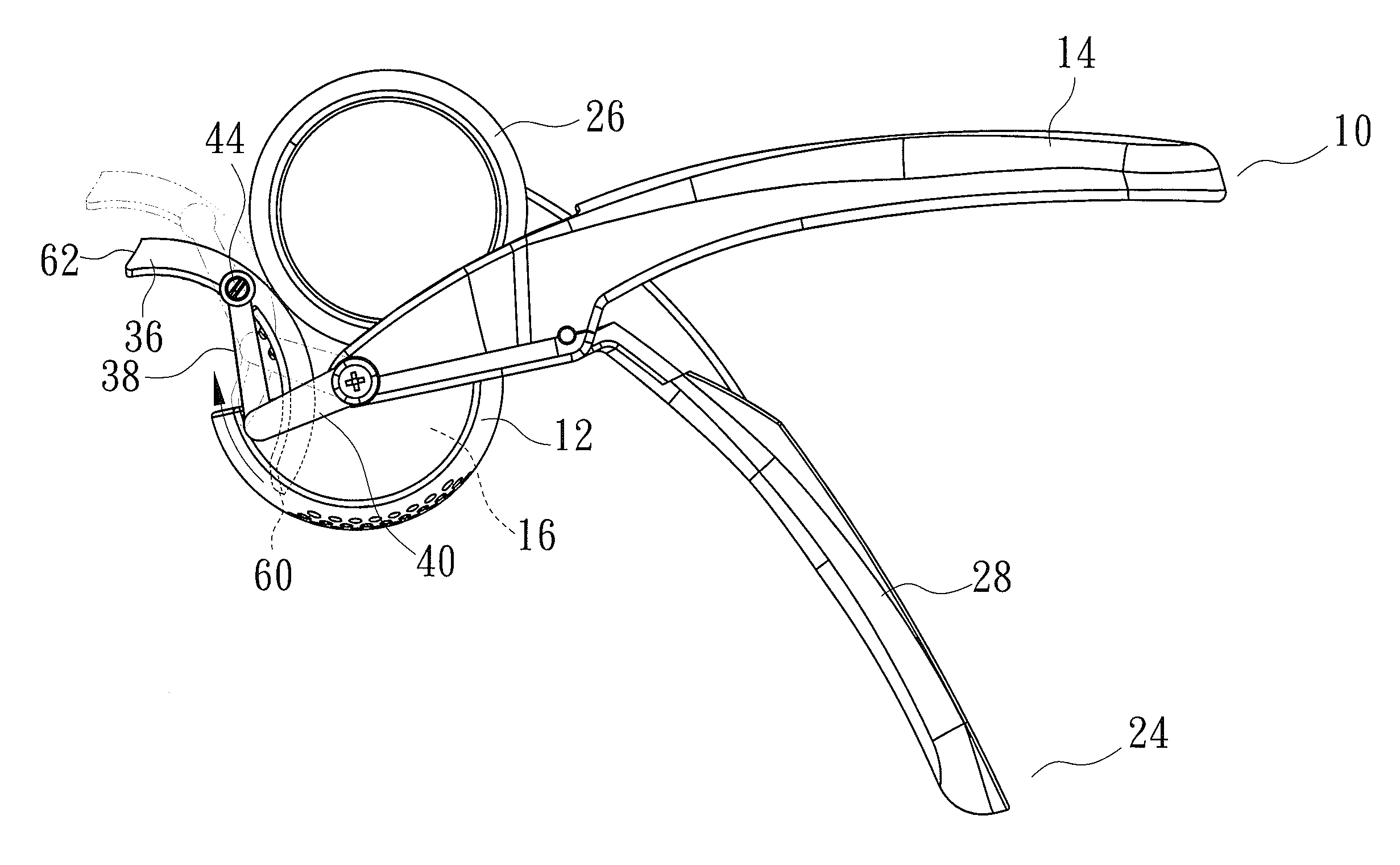
[0024]FIGS. 3 through 9 show a garlic press according to the present invention and including a grip member 10, a crush member 24, and a cleaning device 34. The grip member 10 and the crush member 24 have the same afore-mentioned structures. The crush body 26 can be movably inserted into the housing body 12 for crushing the garlic accommodated inside the chamber 16.

[0025]The cleaning device 34 includes a scraper 36, two first links 38, and two second links 40. The scraper 36 includes a concave inner surface 42, a front edge 60 and a rear edge 62. A pivotal pillar 44 is extended outwardly from each of two sides of the scraper 36. A coupling hole 46 is disposed in each end of each first link 38. A connecting hole 48 is disposed in one end of each second link 40, and a pivotal pillar 50 is disposed at another end of each second link 40. The coupling holes 46 of each first link 38 are pivotally connected with a corresponding pivotal pillar 44 of the scraper 36 and the pivotal pillar 50 o...

third embodiment

[0031]FIG. 10 shows a garlic press according to the present invention and including a grip member 10, a crush member 24, and a detachable scraper 72. The grip member 10 and the crush member 24 have the same afore-mentioned structures. Two slots 70 are provided in a top portion of the crush body 26, and two ends 74 of the scraper 72 are detachably engaged in the slots 70 correspondingly for coupling with the crush body 26. When the garlic press needs to be cleaned, the scraper 72 can be taken off for cleaning out the garlic mash remained on the housing body 12.


PUM


Abstract

A garlic press includes a grip member and a crush member pivotally connected with the grip member. The grip member includes a housing body and an upper handle extended backward from the housing body. The housing body is adapted for accommodating garlic. The crush member includes a crush body which can be movably inserted into the housing body for crushing the garlic into mash. The garlic press may further include a cleaning device which is coupled on a bottom portion of the housing body for cleaning out the garlic mash remained on the housing body. Further, the pivotal point of the garlic press is disposed close to a middle portion of the garlic press structure to make the garlic press to be convenient for using.

Description

BACKGROUND OF THE INVENTION[0001]The present invention relates to a garlic press and, more particularly, to a garlic press allowing remained garlic mash to be cleaned out conveniently.[0002]Garlic press is widely used for crushing garlic. FIG. 11 shows a conventional garlic press A1 which includes a lower supporting member A2 and an upper press member A3. The lower supporting member A2 includes a housing body A4. A connecting portion A5 of the lower supporting member A2 is pivotally connected with a coupling portion A6 of the upper press member A3 by a pin A7, and the pivotal point defined by the pin A7 is at a front end of the lower supporting member A2. When using the garlic press A1, the upper press member A3 is used as an active member for pressing a crush member A8 coupled with the upper press member A3 downward into the housing body A4 for crushing garlic in the housing body A4.[0003]Even though the pivotal point of the garlic press A1 disposing at the front end of the lower s...

Claims


Application Information

Patent Timeline
IPC IPC(8): A47J19/06
CPCA47J19/06A47J19/04
Inventor LEE, TUNG-HSIENSHEN, CHIUNG-HUNG
Owner LEE TUNG HSIEN
Why Eureka
Try Eureka