
Caliper parking brake

Active Publication Date: 2014-01-23
HL MANDO CORP
View PDF3 Cites 9 Cited by
  • Summary
  • Abstract
  • Description
  • Claims
  • Application Information

AI Technical Summary

Benefits of technology

The present invention provides a caliper parking brake that can prevent drag from occurring in a brake disc due to non-return of the piston and a frictional pad pressurized by the piston. Additionally, the invention can compensate for a gap between a brake disc and a frictional pad that is generated by abrasion of the frictional pad in real-time, thus preventing brake defects caused by non-contact between the brake disc and the frictional pad.

Problems solved by technology

As a result, quick return of the frictional pad 105 is disturbed, and although brake has been released, the frictional pad 105 and the brake disc are maintained in a contact state, which results in drag.

Method used


Image

  • Caliper parking brake
  • Caliper parking brake
  • Caliper parking brake

Examples


Embodiment Construction

[0026]Hereinafter, a caliper parking brake according to the present invention will now be described more fully with reference to the accompanying drawings, in which an exemplary embodiment of the invention is shown.

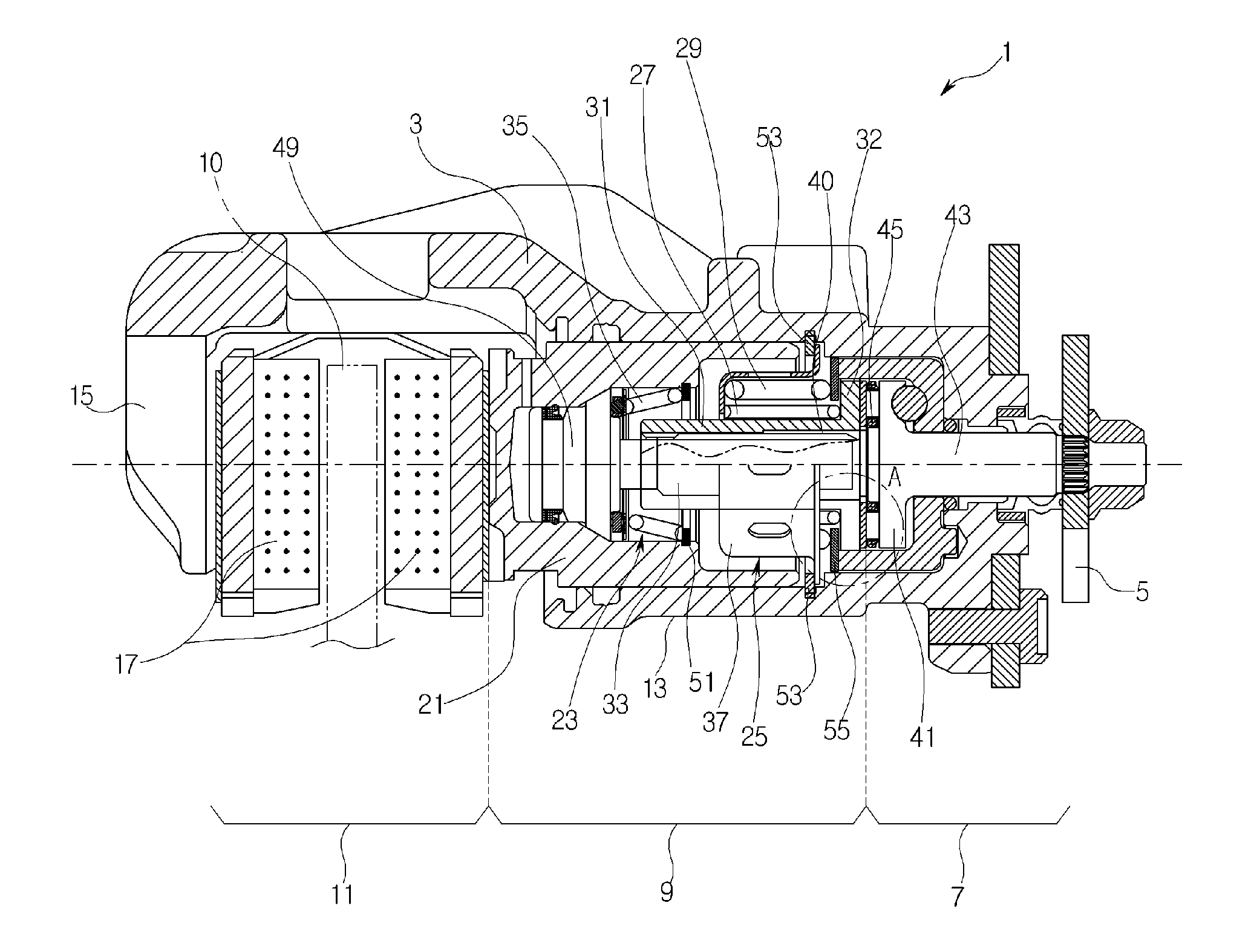
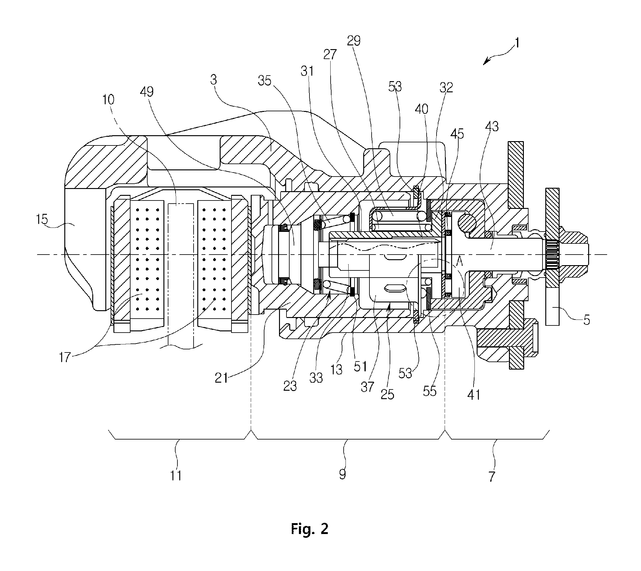
[0027]FIG. 2 is a longitudinal cross-sectional view of a caliper parking brake according to an embodiment of the present invention, FIG. 3 is an exploded perspective view of part of a brake force output terminal illustrated in FIG. 2, FIG. 4 is an enlarged view of a portion A of FIG. 2, and FIG. 5 is an enlarged view for illustrating one-direction screw coupling of a return pipe and an adjustment rod illustrated in FIG. 2.

[0028]Referring to FIG. 2, a caliper parking brake 1 according to the current embodiment of the present invention includes a caliper housing 3, a brake force input terminal 5, a brake force switching terminal 7, a brake force output terminal 9, and a brake terminal 11.

[0029]Here, the caliper housing 3 constitutes the exterior of the caliper parking brake...


PUM


Abstract

A caliper parking brake including: caliper housing having one end on which a cylinder is formed and the other end on which a fork is formed to face the cylinder; brake force input terminal rotatably mounted on an end of the cylinder by a parking cable; brake force switching terminal installed within the cylinder on a common axis so as to rotate together with the brake force input terminal; brake force output terminal directly connected to the brake force switching terminal on a common axis; and a brake terminal that is disposed between the fork and the brake force output terminal and stops rotation of a brake disc using the brake force output by the brake force output terminal, wherein the brake force output terminal compensates for abrasion that occurs in the fork and a frictional pad of the piston by moving an initial position of the piston forward.

Description

CROSS-REFERENCE TO RELATED PATENT APPLICATION[0001]This application claims the benefit of Korean Patent Application No. 10-2012-0079374, filed on Jul. 20, 2012 in the Korean Intellectual Property Office, the disclosure of which is incorporated herein in its entirety by reference.BACKGROUND OF THE INVENTION[0002]1. Field of the Invention[0003]The present invention relates to a caliper parking brake, and more particularly, a caliper parking brake in which a returning force of a piston that returns to a position before brake when brake is released according to a strength of a brake pressure applied to a brake force output terminal increases so that drag that occurs in a brake disc due to non-return of a frictional pad pressurized by the piston can be removed or reduced.[0004]2. Description of the Related Art[0005]In general, caliper-type parking brakes are brakes that perform a brake operation by pressurizing and stopping a brake disc interposed between a piston and a frictional pad of...

Claims


Application Information

Patent Timeline
IPC IPC(8): F16D65/00
CPCF16D65/0075F16D65/18F16D65/567F16D2121/02F16D2121/04F16D55/226F16D65/097F16D65/095
Inventor KONG, YOUNG HUNHONG, SEON KI
Owner HL MANDO CORP
Features
  • Generate Ideas
  • Intellectual Property
  • Life Sciences
  • Materials
  • Tech Scout
  • Unparalleled Data Quality
  • Higher Quality Content
  • 60% Fewer Hallucinations
Learn More