Cyclonic aeolian vortex turbine

a technology of cyclonic aeolian vortex and turbine, which is applied in the direction of machines/engines, renewable energy generation, greenhouse gas reduction, etc., can solve the problem of not intended summary, and achieve the effect of increasing the efficiency of the turbine, increasing the energy of the ingested wind, and reducing the pressure inside the shell

Active Publication Date: 2016-06-21
MONTO MARK T
View PDF22 Cites 14 Cited by
  • Summary
  • Abstract
  • Description
  • Claims
  • Application Information

AI Technical Summary

Benefits of technology

[0010]In an exemplary embodiment a cyclonic aeolian turbine is provided, the turbine having a blade rotor encased into a cavity shell configured to increase the efficiency of the turbine. In an aspect, the shell has an intake opening that takes advantage of the Venturi effect to accelerate the wind ingested into the shell, thus increasing the energy of the ingested wind and decreasing the pressure inside the shell, thus creating a suction effect that pulls more wind into the shell.
[0011]In another aspect, the cavity shell has an airfoil that takes advantage of the Bernoulli effect to contribute to the acceleration of the ingested air and also to increase the ratio of harvested wind.
[0012]In another aspect, the shell has a substantially circular cross-section to take advantage of the Coanda effect to convert the ingested wind into a vortex that constantly approaches the blades at the optimum angle of attack.
[0013]In another aspect, the shell is configured to facilitate the formation of a natural eddy between the vortex and the laminar flow and turbulent flow, outside the path of the blades, thus preventing drag and also contributing to the suction effect.

Problems solved by technology

Moreover, this Summary is not intended for use as an aid in determining the scope of the claimed subject matter.

Method used


Image

  • Cyclonic aeolian vortex turbine
  • Cyclonic aeolian vortex turbine
  • Cyclonic aeolian vortex turbine

Examples


Embodiment Construction

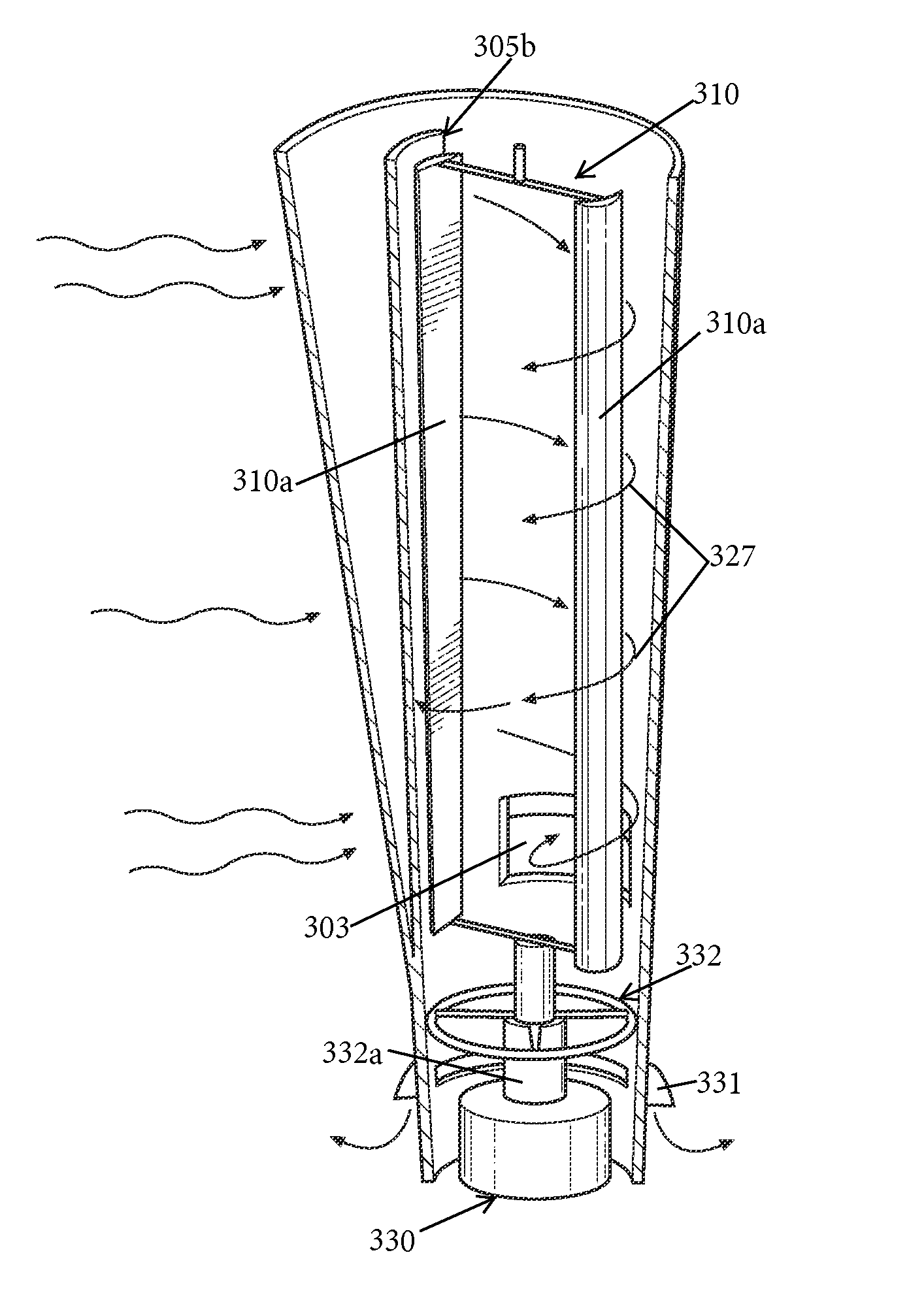
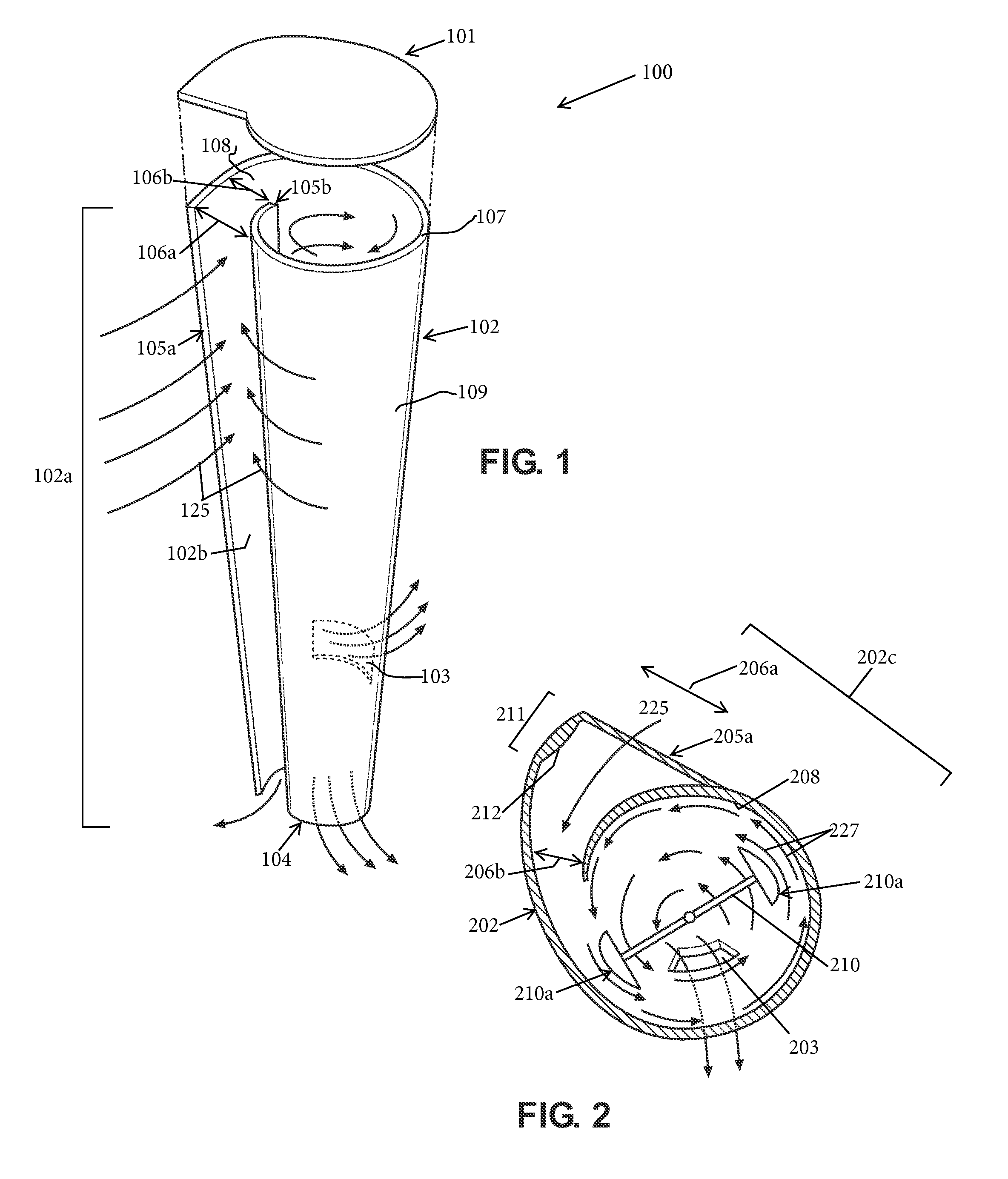
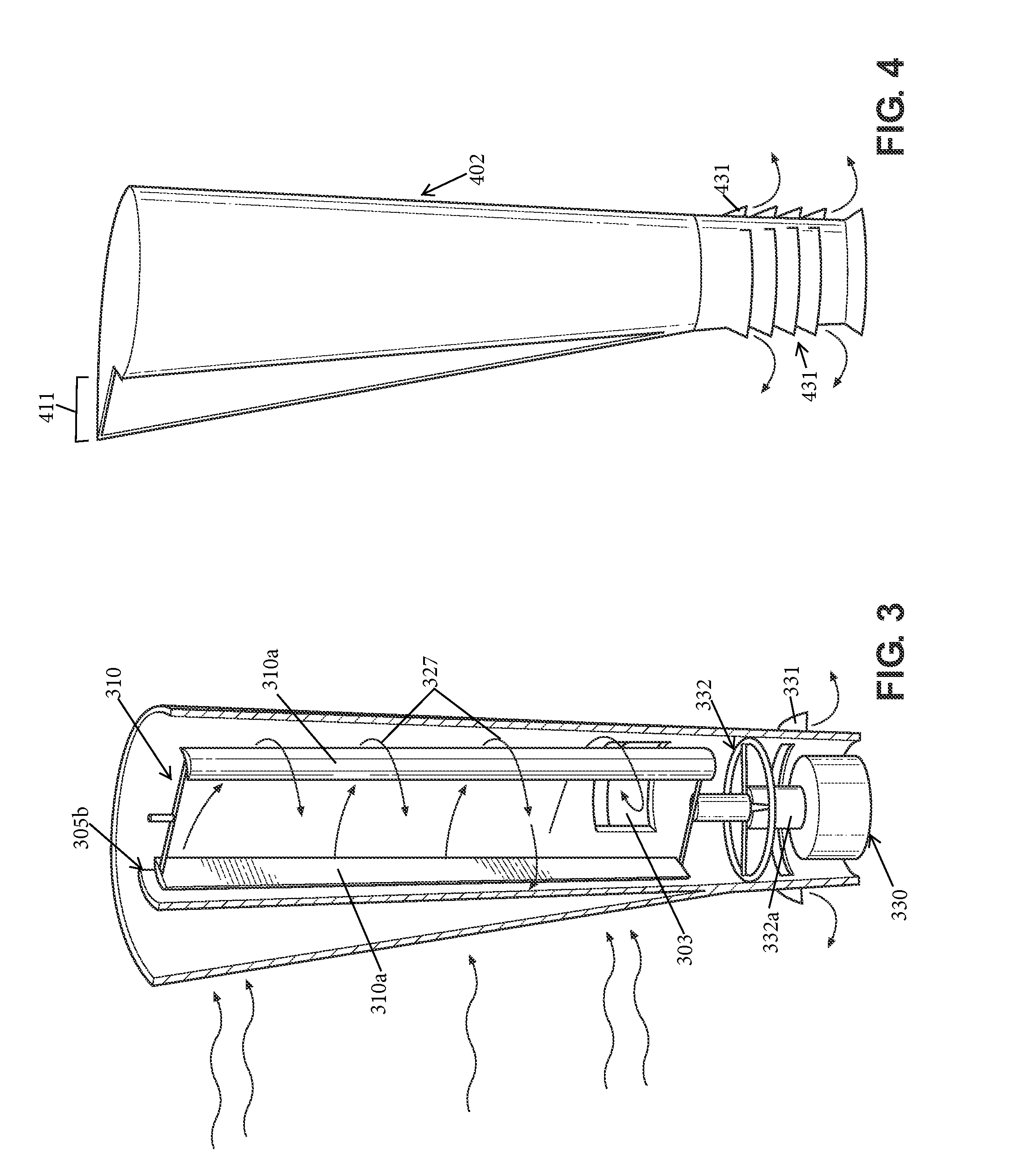
[0061]What follows is a detailed description of the preferred embodiments of the invention in which the invention may be practiced. Reference will be made to the attached drawings, and the information included in the drawings is part of this detailed description. The specific preferred embodiments of the invention, which will be described herein, are presented for exemplification purposes, and not for limitation purposes. It should be understood that structural and / or logical modifications could be made by someone of ordinary skills in the art without departing from the scope of the invention. Therefore, the scope of the invention is defined by the accompanying claims and their equivalents.

[0062]For the following description, it can be assumed that most correspondingly labeled elements across the figures (e.g., 102 and 202, etc.) possess the same characteristics and are subject to the same structure and function. If there is a difference between correspondingly labeled elements that...


PUM


Abstract

A wind turbine is provided that has a blade encased into a substantially circular portion of a shell, the shell having an interior surface, an exterior surface, a first end, an opposite second end, and an intake opening between the first and the second end, wherein the first end is closed and wherein the shell has an exhaust opening at or near the second end, wherein wind ingested into the shell through the intake opening is forced to become a vortex having a higher speed than the ingested wind and concentrating the ingested wind substantially near the interior surface of the shell into a spiral air stream traveling toward the exhaust opening, in order to increase an amount of energy harvested by the blade from the ingested wind before the ingested wind, devoid of the amount of energy harvested, exits the shell through the exhaust opening.

Description

BACKGROUND OF THE INVENTION[0001]1. Field of the Invention[0002]The invention relates generally to wind turbines and more particularly to methods, systems and apparatus for increasing the efficiency of wind turbines.[0003]2. Description of the Related Art[0004]Horizontal Wind Turbines (HWT) have several negatives, such as bird strikes, having the generator mounted high with blades, which increases maintenance costs, “blades noise” and “flicker,” the flicker being caused by large HWT blades passing in front of sunlight. HWT are also known for “Ice Throws, which are large build ups of ice on the blades during winter months that can be ejected at high speed and long distances causing damage or harm to people or property. Further, because of the above drawbacks of the HWT, their placement restrictions, away from populations and homes, are currently implemented around the world.[0005]Some of the largest Horizontal Wind Turbines have a rotor diameter of 70 m and tower height of 130 m and ...

Claims


Application Information

Patent Timeline
Patent Type & Authority Patents(United States)
IPC IPC(8): F03D3/04
CPCF03D3/0427F03D3/0409F03D3/0463F03D3/049F03D9/39F05B2240/132Y02E10/728Y02E10/74
Inventor MONTO, MARK T.
Owner MONTO MARK T
Why Eureka
Try Eureka